5.2.1.7. Interlaken Disparity Generator
The Interlaken disparity generator block is in accordance with the Interlaken protocol
specification and provides a DC-balanced data output.
The Interlaken protocol solves the unbounded baseline wander, or DC imbalance, of
the 64B/66B coding scheme used in 10Gb Ethernet by inverting the transmitted data.
The disparity generator monitors the transmitted data and makes sure that the
running disparity always stays within a ±96-bit bound. It adds the 67th bit (bit 66) to
signal the receiver whether the data is inverted or not.
Table 255. Inversion Bit Definition
Bit 66 Interpretation
0 Bits [63:0] are not inverted; the receiver processes this word without modification
1 Bits [63:0] are inverted; the receiver inverts the bits before processing this word
Note: The Interlaken disparity generator is available to implement the Interlaken protocol.
5.2.1.8. TX Gearbox, TX Bitslip and Polarity Inversion
The TX gearbox adapts the PCS data width to the smaller bus width of the PCS-PMA
interface (Gearbox Reduction). It supports different ratios (FPGA fabric-PCS Interface
Width: PCS-PMA Interface Width) such as 66:32, 66:40, 64:32, 40:40, 32:32, 64:64,
67:64, and 66:64. The gearbox mux selects a group of consecutive bits from the input
data bus depending on the gearbox ratio and the data valid control signals.
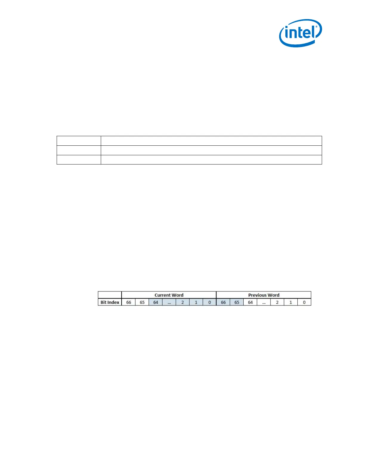
The TX gearbox also has a bit slipping feature to adjust the data skew between
channels. The TX parallel data is slipped on the rising edge of tx_enh_bitslip
before it is passed to the PMA. The maximum number of the supported bitslips is PCS
data width-1 and the slip direction is from MSB to LSB and from current to previous
word.
Figure 243. TX Bitslip
tx_enh_bitslip = 2 and PCS width of gearbox is 67
You can use transmitter data polarity inversion to invert the polarity of every bit of the
input data word to the serializer in the transmitter path. The inversion has the same
effect as swapping the positive and negative signals of the differential TX buffer. This
is useful if these signals are reversed on the board or backplane layout. Enable
polarity inversion through the Native PHY IP Parameter Editor.
5.2.1.9. KR FEC Blocks
The KR FEC blocks in the Enhanced PCS are designed in accordance with the 10G-
KRFEC and 40G-KRFEC of the IEEE 802.3 specification. The KR FEC implements the
Forward Error Correction (FEC) sublayer, a sublayer between the PCS and PMA
sublayers.
5. Arria 10 Transceiver PHY Architecture
UG-01143 | 2018.06.15
Intel
®
Arria
®
10 Transceiver PHY User Guide
469