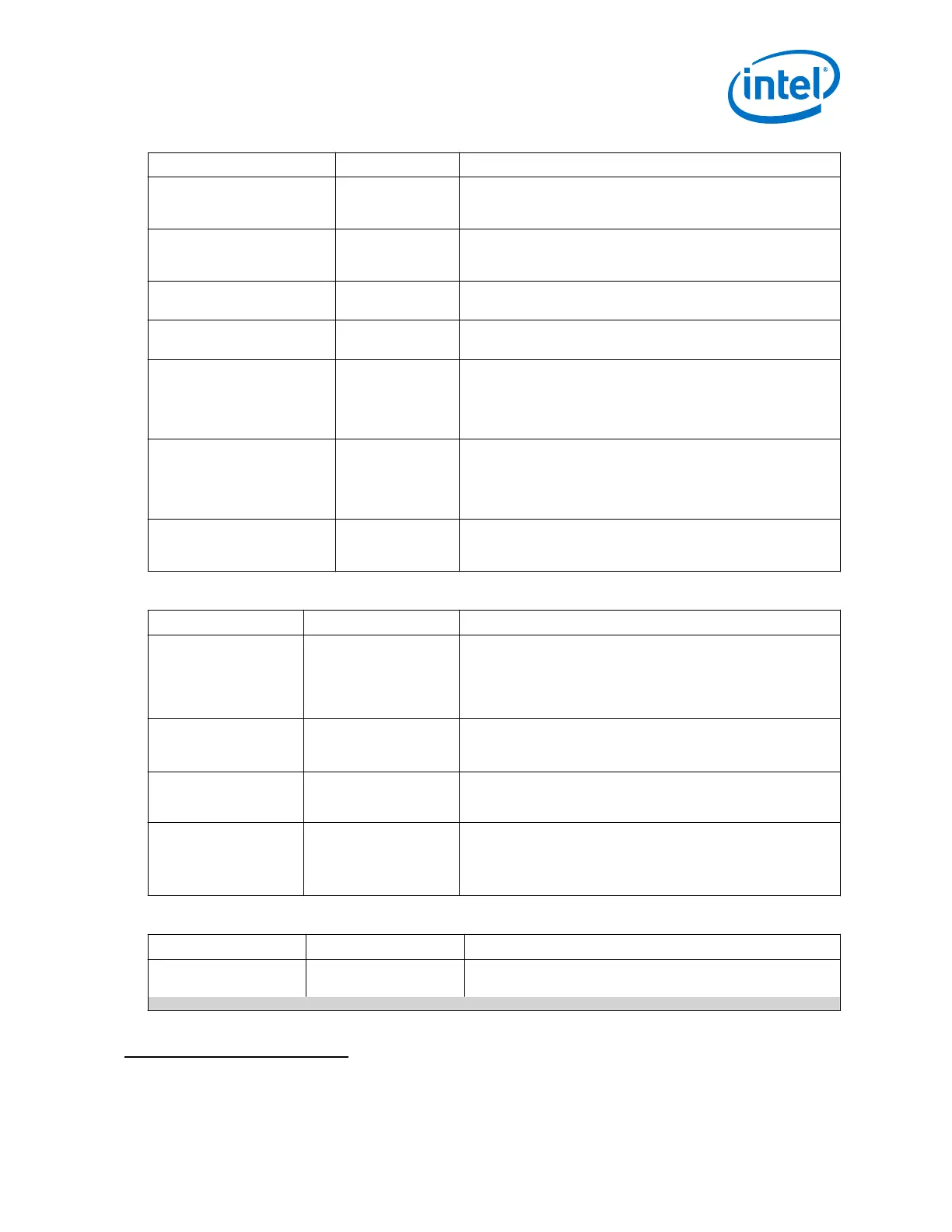
Parameter Value Description
Enable
tx_pma_iqtxrx_clkout port
On/Off
Enables the optional tx_pma_iqtxrx_clkout output clock. This
clock can be used to cascade the TX PMA output clock to the input
of a PLL.
Enable tx_pma_elecidle
port
On/Off
Enables the tx_pma_elecidle port. When you assert this port,
the transmitter is forced into an electrical idle condition. This port
has no effect when the transceiver is configured for PCI Express.
Enable tx_pma_qpipullup
port (QPI)
On/Off
Enables the tx_pma_qpipullup control input port. Use this port
only for Quick Path Interconnect (QPI) applications.
Enable tx_pma_qpipulldn
port (QPI)
On/Off
Enables the tx_pma_qpipulldn control input port. Use this port
only for QPI applications.
Enable tx_pma_txdetectrx
port (QPI)
On/Off
Enables the tx_pma_txdetectrx control input port. The receiver
detect block in the TX PMA detects the presence of a receiver at
the other end of the channel. After receiving a
tx_pma_txdetectrx request the receiver detect block initiates
the detection process. Use this port only in QPI applications.
Enable tx_pma_rxfound
port (QPI)
On/Off
Enables the tx_pma_rxfound status output port. The receiver
detect block in TX PMA detects the presence of a receiver at the
other end by using the tx_pma_txdetectrx input. The
tx_pma_rxfound port reports the status of the detection
operation. Use this port only in QPI applications.
Enable rx_seriallpbken port On/Off
Enables the optional rx_seriallpbken control input port. The
assertion of this signal enables the TX to RX serial loopback path
within the transceiver. This is an asynchronous input signal.
Table 14. RX CDR Options
Parameter Value Description
Number of CDR
reference clocks
1 - 5 Specifies the number of CDR reference clocks. Up to 5 sources are
possible.
The default value is 1.
Use this feature when you want to dynamically re-configure CDR
reference clock source.
Selected CDR
reference clock
0 to <number of CDR
reference clocks> -1
Specifies the initial CDR reference clock. This parameter
determines the available CDR references used.
The default value is 0.
Selected CDR
reference clock
frequency
< data rate dependent > Specifies the CDR reference clock frequency. This value depends
on the data rate specified.
PPM detector
threshold
100
300
500
1000
Specifies the PPM threshold for the CDR. If the PPM between the
incoming serial data and the CDR reference clock, exceeds this
threshold value, the CDR loses lock.
The default value is 1000.
Table 15. Equalization
Parameters Value Description
CTLE adaptation mode Manual Specifies the Continuous Time Linear Equalization (CTLE)
operation mode.
continued...
(25)
The default value is Disabled.
2. Implementing Protocols in Arria 10 Transceivers
UG-01143 | 2018.06.15
Intel
®
Arria
®
10 Transceiver PHY User Guide
53