130 Keysight M8000 Series of BER Test Solutions User Guide
4 User Interface - M8020A Display Views
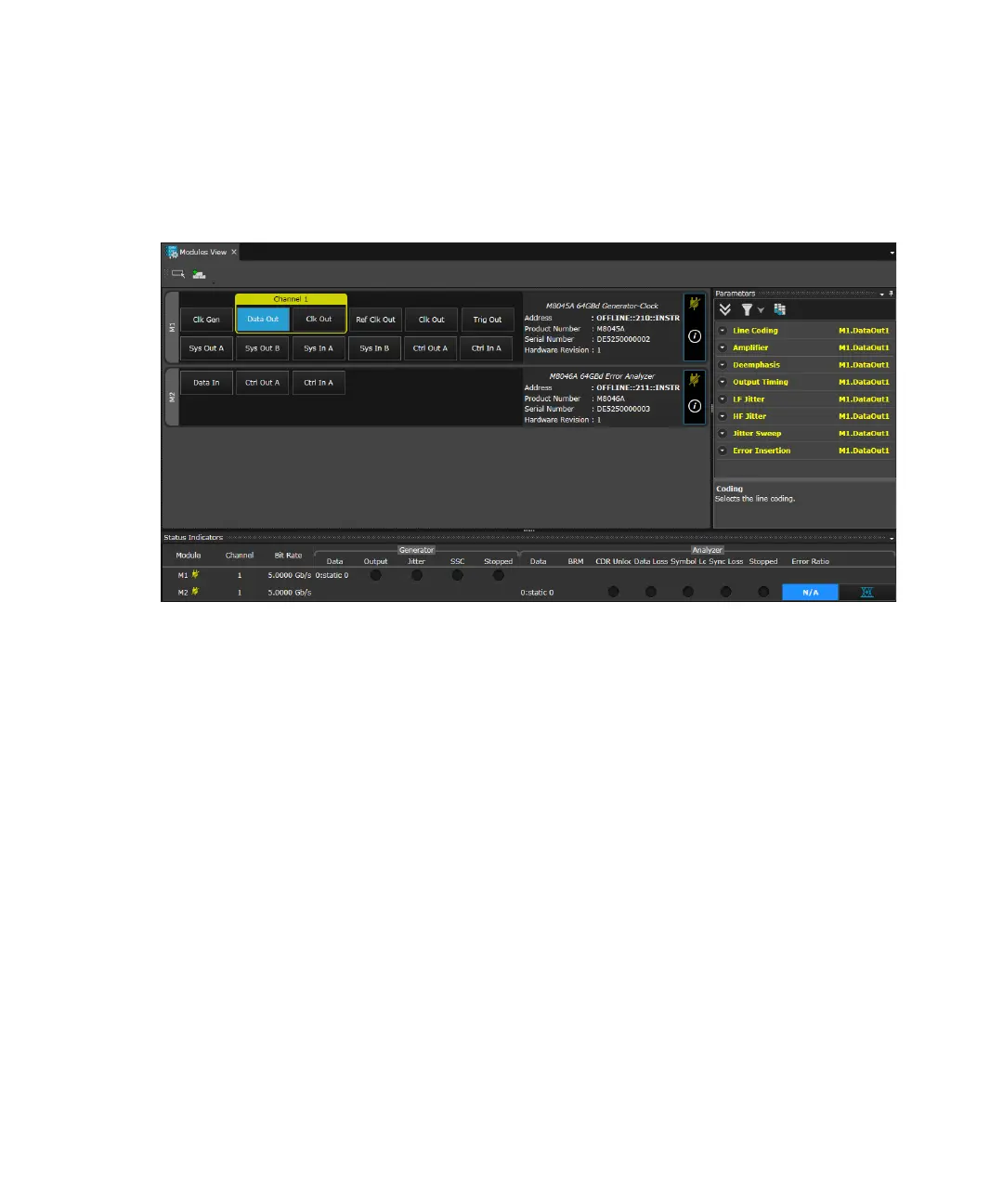
The following figure shows an example of Module View when M8045A
(M1) and M8046A (M2) modules are connected:
Input and Output Ports
M8041A and M8051A Modules
The M8041A (8.5/16G Generator, Analyzer, Clock Module) and M8051A
(Generator-Analyzer) modules can have the following input and output
ports:
• Clock Gen: Clock can be generated from the internal oscillator or an
external source.
• Data Out: Data Out acts as the output port for the Generator which
may be connected to the DUT. The data outputs serve as device stimuli
and can be set up so that they are compatible with a variety of logic
families.
• Data In: Data In acts as the input port for the Analyzer. This port is
connected to the data signal which is the output of the DUT. Here the
signal received and the signal generated internally is compared for
calculating the bit error ratio.

 Loading...


