Keysight M8000 Series of BER Test Solutions User Guide 265
Setting up Generator 5
Step 3 If the Measured Voltage for P is OFFSET +50 mV and for N is OFFSET -50
mV -> Pass. Turn on the output driver. However, this is false if DUT is not
connected or AC coupled.
Adjust Output Levels (optional)
Data, Clock and Trigger Out offset and voltage levels can be adjusted. This
is typically done when you want to tune your BER measurement or stress
the device.
You can adjust the related parameters of the data and clock amplitudes
and offsets on the GUI.
To enter specific values for the outputs from the keyboard:
1Go to the Menu Bar > Generator and then select Data Out and Trigger
Out ports. Once more, go to the Menu Bar > Generator and then select
Clock Out port.
2 Select Amplifier functional block from the Parameters window.
3 Select coupling as DC.
4 Select termination model as Unbalanced.
5 Enter the desired termination voltage.
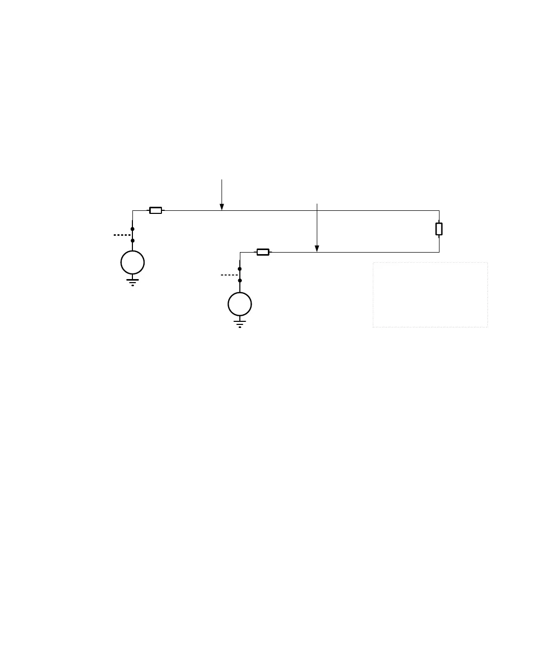
V
Measured Voltage for P = OFFSET +50 mV and N = OFFSET -50 mV → Pass
VCCO P = OFFSET +100 mV
V
VCCO N = OFFSET -100 mV
Closed
Switch
Internal 50 Ohm
Legends
VT – Termination Voltage
P – Normal (Non-Inverted)
N – Complement (Inverted)
VCCO – Output Voltage Power Supply
DUT – Device Under Test
This is false if DUT is not connected or AC coupled
Closed
Switch
DUT 100 Ohm
Internal 50 Ohm

 Loading...


