176 Keysight M8000 Series of BER Test Solutions User Guide
4 User Interface - M8020A Display Views
Features of the Impairment Setup View
In this tabular matrix of the Impairment Setup View, the rows consist of
the Impairment Sources, their corresponding options and their related
parameters. The columns represents channels Data Out, Clock and Trigger
parameters for each channel.
Columns
Each channel of a module is represented using a particular color code,
which form the column header and they correspond to the color-coding
used for that channel in the Modules View. See Module View on page 127.
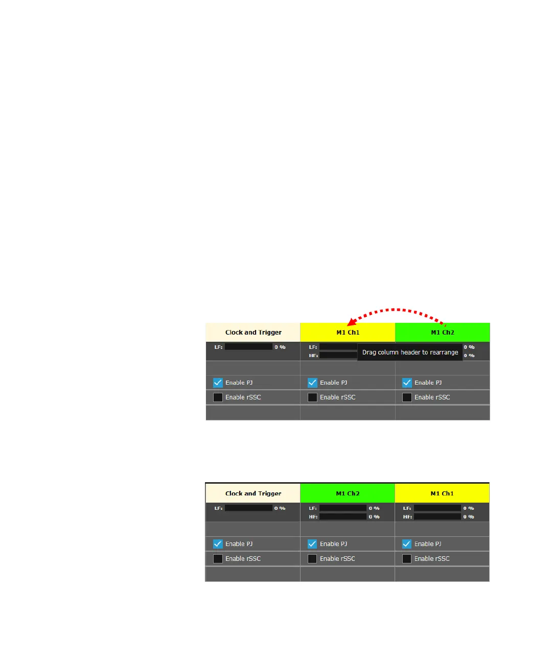
You may rearrange the column headers by clicking and dragging a header
to the desired position.
For example, if you want to view the settings of M1Ch2 first, then click and
hold the cursor on M1 Ch2, drag it to the right and release the cursor at
the desired position.
The Impairment Setup View will now show the channel position as shown
in the following figure:

 Loading...


