Keysight M8000 Series of BER Test Solutions User Guide 53
Know Your Hardware 2
Table 27 Sync In/Clean Clk Out
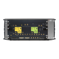
M8062A Front Panel Pattern Generator Connectors
Table 28 Electrical Idle Input
Table 29 Pattern Generator Clock Inputs/Output
Table 30 DMI/CMI Inputs
Connector Name Description
Sync In This input is used to synchronize two or more modules to a common system clock. It is connected to the Sync
Out of the other module. The sync cable is required if M8062A is connected with M8041A module.
Clean Clk Out Half-rate, or divided, clock output with no applied jitter.
Component Description
Electrical Idle In This input is used to enable/disable the output signal by an external control signal. If the input level is above the
threshold level the module enters electrical idle. Normal operation resumes when the input level is below the
threshold (SMA, female).
Component Description
Clk Out Half-rate Pattern Generator clock output. Carries the same jitter as the full-rate data output.
Clk In Pattern Generator clock input (half-rate). Connect to clock output of M8041A.
Aux Clk In Alternate Pattern Generator clock input (half-rate). Typically unused.
Component Description
DMI In Differential Mode Interference input. Applies a single-ended, external interference source differentially to the
data output (SMA, female).
CMI In Common Mode Interference input. Applies a single-ended, external interference source to both the normal and
complement data output signals (SMA, female).

 Loading...


