162 Keysight M8000 Series of BER Test Solutions User Guide
4 User Interface - M8020A Display Views
System View with M8061A Integration
This section describes the block diagrams provided by the System View
when M8061A is integrated with other modules of M8020A.
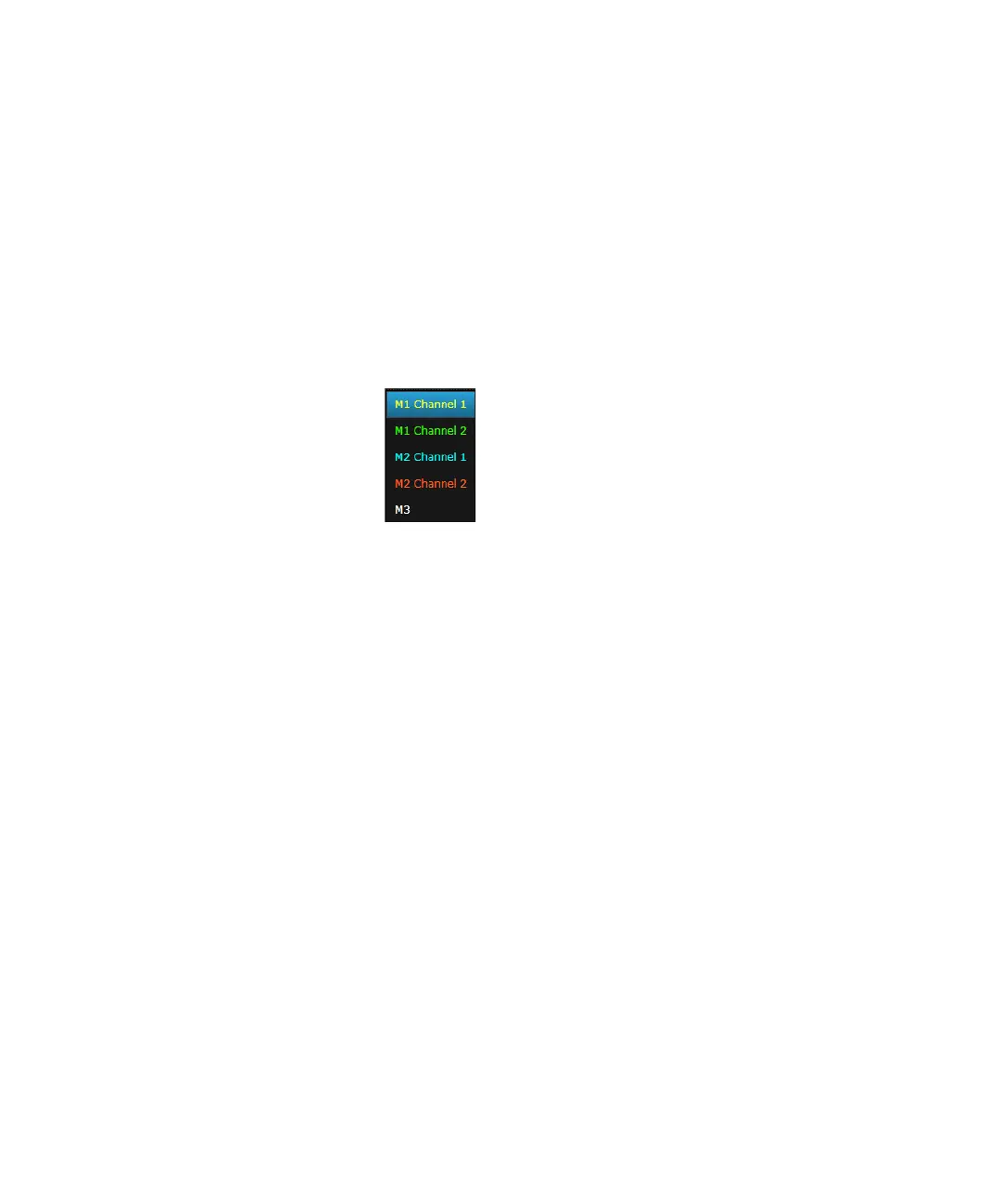
Channels
Displays the channels that are connected to the M8020A. The following
figure shows M1 (2 channels of M8041A), M2 (2 channels of M8051A) and
M3 (M8061A) modules connected to the instrument.
When you select the channel, the corresponding block diagram of that
channel appears which allows you to interactively configure channel
settings. You can also assign a different color to each channel so that they
are easily identified. For details, refer to Settings Window on page 602.
Integration Modes
The System View with M8061A integration provides the following modes:
• Standalone Mode
• Mux Only Mode
• Demux Only Mode
• Mux and Demux Mode
Standalone Mode
The Standalone mode is used to set the parameters of the Data Out port
of M8041A module and Data In port of M8061A module.
The following figure shows the block diagram of M8041A module in
Standalone mode:

 Loading...


