52 Keysight M8000 Series of BER Test Solutions User Guide
2 Know Your Hardware
M8062A Module Components
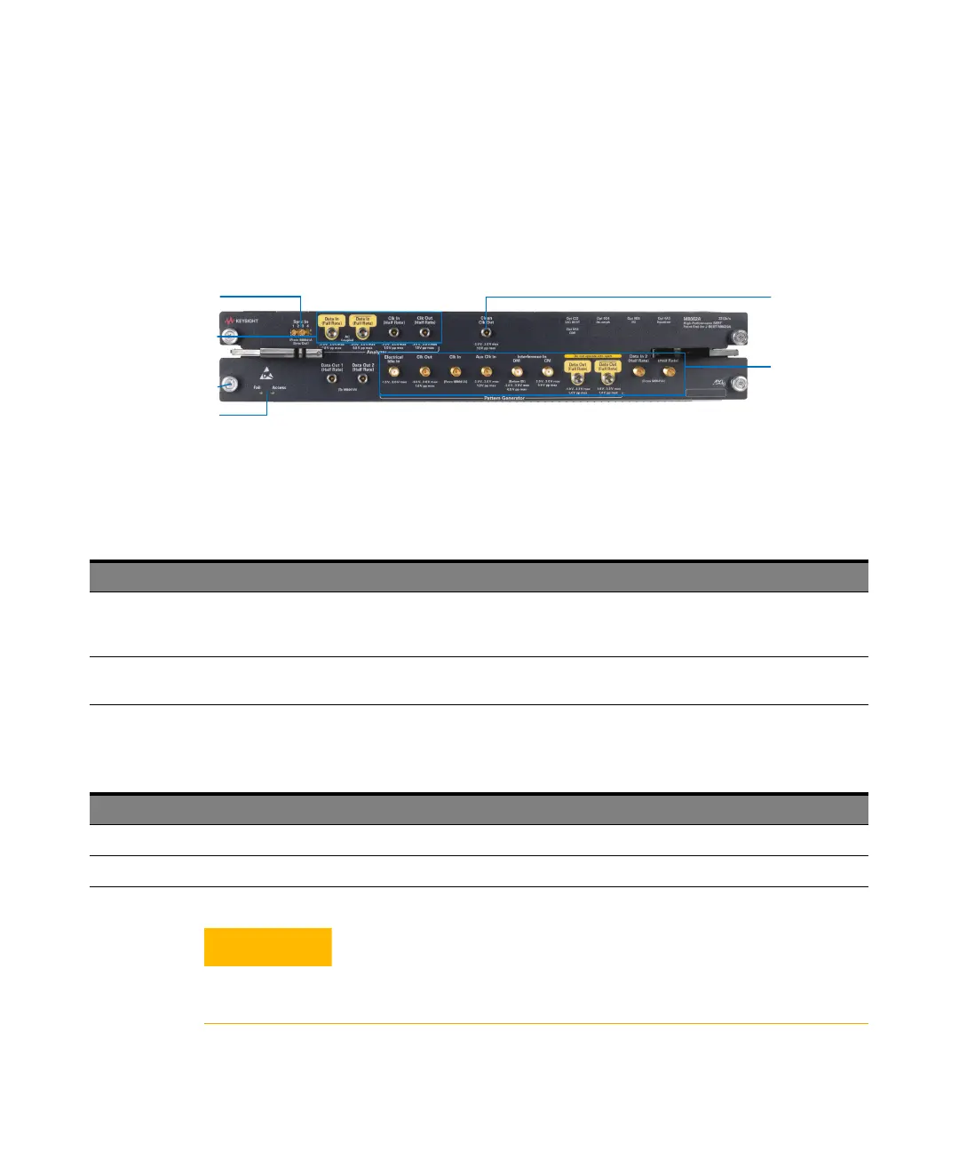
The following figure displays the front panel of the M8062A module with its
various components labeled.
The M8062A module has the following components.
Table 25 Insertion/Extraction and Retaining
Table 26 Front Panel LEDs
Front Panel LEDs
Sync In
Retaining Screws
Clean Clk Out
M8062A Front
Panel Error
Analyzer Connectors
M8062A Front
Panel Pattern
Generator
Connectors
Component Description
Retaining screws The screws on both ends of the module are used to retain the module tightly inside the M9505A AXIe
Chassis slot once you have fully placed it inside the chassis. To remove the module, you first need to
loosen these screws ensuring that these screws disengage completely.
Module Insertion/Extraction Handles The handles on both sides of the module to insert or eject the module from the slot of the M9505A AXIe
Chassis.
Connector Name Active when... Color
Fail power-up fault condition red
Access power-up ready state green
The inputs and outputs of the M8062A module are sensitive to static
electricity. Therefore, take necessary anti-static precautions, such as
wearing a grounded wrist strap, to minimize the possibility of
electrostatic damage.