260 Keysight M8000 Series of BER Test Solutions User Guide
5 Setting up Generator
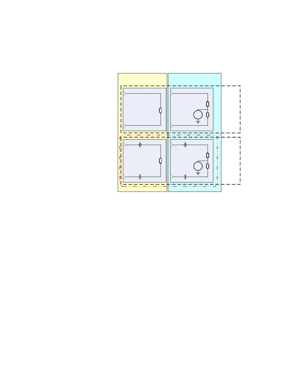
The following drawing is an example of the external DUT connected to the
generator output for the different possible settings.
This figure shows what the generator expects to be externally connected
as DUT, with respect to the different selectable termination models.
For AC-coupled mode (see red box above), the instrument actually cannot
and does not need to distinguish between these two termination schemes.
Therefore the drop-down box Termination Model is not shown and active
within the GUI when the AC coupled mode is selected.
There are certain impedance/voltage limits you need to keep in order to be
able to turn on (enable) the output(s).
Whenever an output amplifier is turned on, the external DC resistance as
well as the external termination voltage is measured and calculated.
These are the impedance/voltage limits for various modes /
configurations:
• DC Coupling Unbalanced: The measured externally connected
resistance should be within the allowed range which is between
40 to 65 here. Also, if an external termination voltage is detected
that is not within the allowed ±100 mV tolerance window, the output(s)
will not turn on.
DUT
DUT
DUT
VT
DUT
VT
Balanced Unbalanced
DC
AC
GENERATOR
VT = Termination Voltage

 Loading...


