Keysight M8000 Series of BER Test Solutions User Guide 319
Setting up Analyzer 6
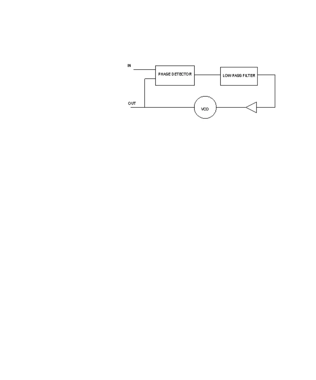
One of the most important characteristics of a PLL is its loop transfer
function.The loop bandwidth is defined as the integrated magnitude of the
PLL’s frequency transfer function over the entire frequency spectrum. The
loop bandwidth describes how the regulatory loop tracks the VCO to a sine
wave FM modulated input signal. Above the bandwidth the loop cannot
track such a modulation completely, and thus, the response to the
modulation is attenuated.
The other loop parameter is peaking. This describes how much a
modulation is exaggerated (mostly close to the loop bandwidth).
Transition Density
The transition density is defined by the number of transitions in the
incoming data divided by the total number of bits transmitted. In this field
enter the transition density in (%).
This parameter affects the loop bandwidth, and thus must be entered
correctly. Some standards specify the loop bandwidth for a given
transition density. In such a case enter the value given in the specification,
so that the CDR behaves according to the standard. If a standard from the
preset list is selected, this field is also preset.
Loop Bandwidth
This is the range of the CDR loop bandwidth. In this field the user should
enter the loop bandwidth value; the range is within 313 kHz to 20 MHz.
When the M8020A/M8030A Analyzer is used to characterize a data stream
instead of a receiver, the loop parameters should be set according to the
used standard.
If the CDR is used to recover the bit stream from a receiver to be
characterized due to a lack of a clock output, choose the loop bandwidth
significantly higher than the receiver’s bandwidth. To characterize a DUT’s

 Loading...


