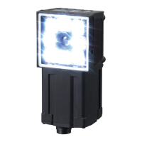
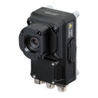
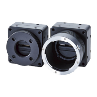
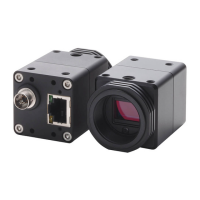
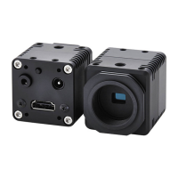
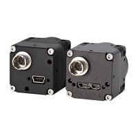
Specifications and Dimensions
FQ2-S/CH User’s Manual
555
Appendices
9
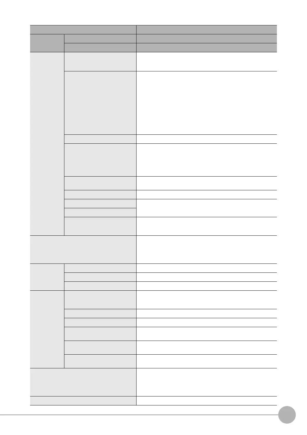
I/O specifica-
tions
Input signals 7 signals
• Single measurement input (TRIG)
• Control command input (IN0 to IN5)
Output signals 3 signals
• Control output (BUSY)
• Overall judgement output (OR)
• Error output (ERROR)
Note: The assignments of the three output signals (OUT0 to OUT2) can
also be changed
to the following.
・READY
・RUN
・STG (Strobe trigger)
・OR (Item0 judgment) to OR31 (Item31 judgment)
・Exp.0 judgment to Exp.31 judgment
Ethernet specifications 100Base-TX/10Base-T
Communications Ethernet TCP no-protocol,
Ethernet UDP no-protocol,
Ethernet FINS/TCP no-protocol,
EtherNet/IP,
PLC Link, or
PROFINET
I/O expansion Possible by connecting FQ-SDU1 Sensor Data Unit..
11 inputs and 32 outputs
RS-232C Possible by connecting FQ-SDU2 Sensor Data Unit..
Input specifications
Refer to Table 2.
Output specifications
Connection method Special connector cables
Power supply and I/O: 1 cable (FQ-WD)
Touch Finder and computer: 1 cable (FQ-WN)
Indications BUSY indicator (BUSY, green), Judgement result indicator (OR, orange),
error indicator (ERROR, red), Ethernet communications indicator (ETN,
orange)
Note: The assignment of the BUSY indicator can be changed to a RUN indi-
cator (display color: green).
Ratings Power supply voltage 21.6 to 26.4 VDC (including ripple)
Insulation resistance Between all lead wires and case: 0.5 MΩ (at 250 V)
Current consumption 2.4 A max.
Environmental
immunity
Ambient temperature range Operating: 0 to 50°C
Storage: −25 to 65°C
(with no icing or condensation)
Ambient humidity range Operating and storage: 35% to 85% (with no condensation)
Ambient atmosphere No corrosive gas
Vibration resistance (destruction) 10 to 150 Hz, single amplitude: 0.35 mm, X/Y/Z directions
8 min each, 10 times
Shock resistance (destruction) 150 m/s
2
3 times each in 6 direction (up, down, right, left, forward, and
backward)
Degree of protection IEC 60529 IP67 (Except when Polarizing Filter Attachment is mounted or
connector cap is removed.)
Materials Sensor: PBT, PC, SUS
Mounting Bracket: PBT
Polarizing Filter Attachment: PBT, PC
Ethernet connector: Oil-resistance vinyl compound
I/O connector: Lead-free heat-resistant PVC
Weight Depends on field of view and installation distance. Refer to Table 1.
Item Inspection and ID models
Model NPN FQ2-CH10-M
PNP FQ2-CH15--M

 Loading...

