ELECTRICAL COMPONENT LAYOUT
SM 3 B544
1 Bin Tray
B544
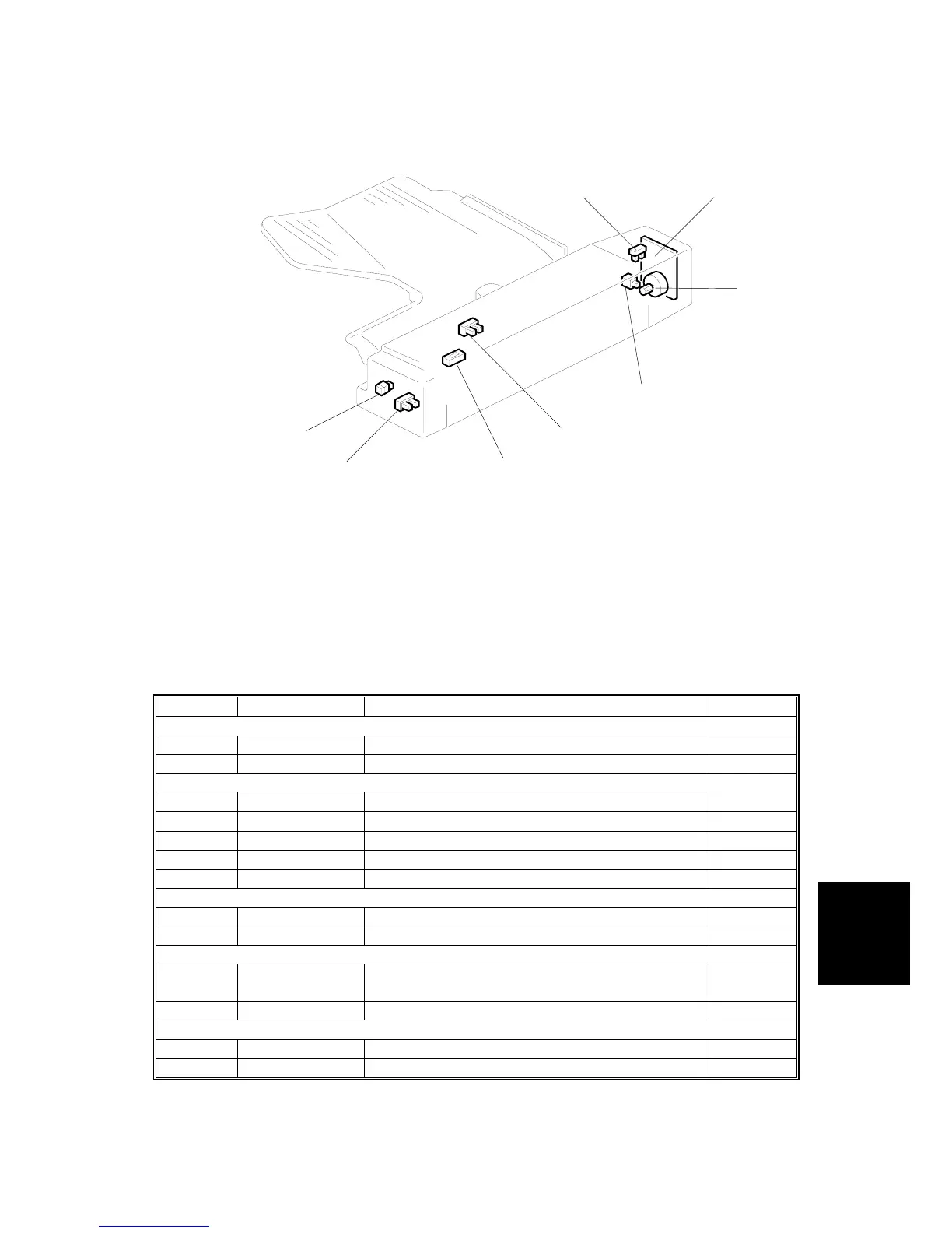
1.3 ELECTRICAL COMPONENT LAYOUT
1. Motor Lock Sensor
2. Main Board
3. Tray Motor
4. Right Cover Switch
5. Paper Limit Sensor
6. Paper Sensor
7. Entrance Sensor
8. Paper Indicator
1.4 ELECTRICAL COMPONENT DESCRIPTION
Symbol Name Function Index No.
Motors
M1 Tray Drives the entrance and exit rollers. 3
Sensors
S1 Entrance Checks for misfeeds. 7
S2
Paper Limit Detects the paper stack limit in the tray.
5
S3 Paper Detects whether there is paper in the tray. 6
S4 Motor Lock Detects whether the tray motor is turning. 1
Switches
SW1 Right Cover Detects whether the right cover is opened. 4
PCBs
PCB1
Main Controls the 1-bin tray and communicates
with the copier.
2
LEDs
LED1 Paper Indicator Indicates when there is paper in the tray. 8
B376V502.WMF
4
8
7
6
5
3
2
1