Doc. Rev. 1.0.21 en-US
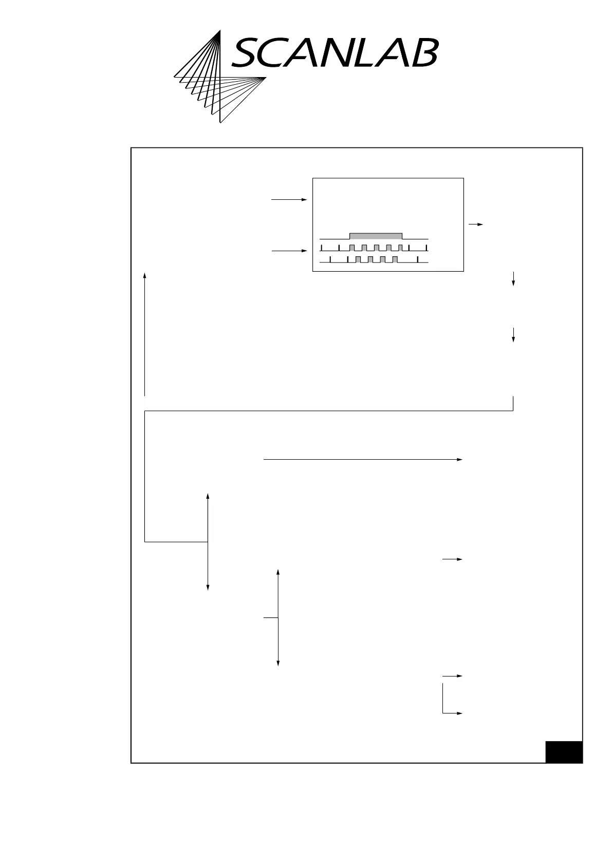
LASER2
LASER1
LASERON
Case LASERON = “OFF“:
There are signals for
“Laser standby” operation
Case LASERON = “ON“:
There are signals for
“Laser active” operation
The signals for the “Laser active” operation and/or
“Laser standby” operation have been specified in advance
= YES
There is permanently
the „OFF“ level
The signals for the “Laser active” operation and/or
“Laser standby” operation have been specified in advance
= NO
enable_laser
or
set_laser_control
(Bit #02 = 0 of Bitmask)
There are permanently
signals for
“Laser standby” operation
disable_laser
or
set_laser_control
(Bit #02 = 1 of Bitmask)
load_program_file
resets
Transfer to the
pin for LASERON
pin for LASER1
pin for LASER2
is irreversibly
UNBLOCKED
set_laser_control(Bitmask)
(specify polarity by
Bit #3 & Bit #4 of Bitmask).
The one time call unblocks irreversibly
Transfer to the
pin for LASERON
pin for LASER1
pin for LASER2
is BLOCKED
RTC6-FPGA (chip)
generates internally
signals for “Laser active” operation &
signals for “Laser standby“ operation
as specified (Example: CO
²
Mode)
set_standby( HalfPeriod, PulseLength )
Specify output period and pulse length of
LASER1 and LASER2
in “Laser standby” operation
set_laser_pulses( HalfPeriod, PulseLength )
Specify output period and pulse length of
LASER1 and LASER2
in “Laser active” operation