RTC6 boards
Doc. Rev. 1.0.21 en-US
7 Basic Functions for Scan Head Control and Laser Control
140
7.1.2 Microstepping
The RTC6 PCIe Board splits up each
• Jump Command,
• [*]mark[*] Command and
• “Arc” Command
into so-called
• Microsteps
(not: Microvectors, see Chapter 8.8
”micro_vector[*] Commands”, page 273).
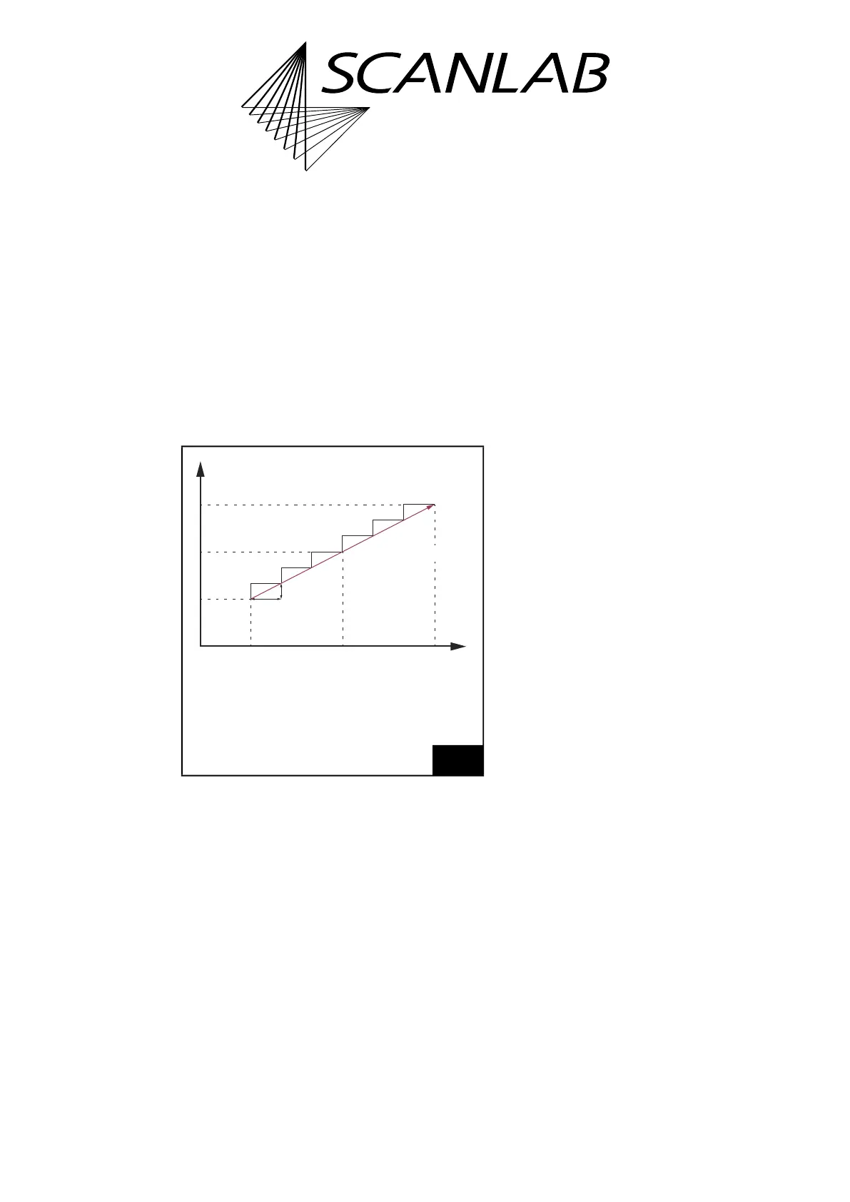
The split-up of the x component of a vector into
Microsteps is shown in Figure 34.
All Microsteps are transferred to the scan head with
a constant output interval (t) of 10 µs and cannot be
changed.
The following applies:
Length s of a Microstep = v × t
(1)
(v = current jump speed or mark speed)
Notes
• Custom curves can be implemented by using
micro_vector[*] Commands, see Chapter 8.8
”micro_vector[*] Commands”, page 273.
• Only iDRIVE scan systems
(2)
which are equipped
with an appropriate tuning can execute jumps
also in Jump Mode, see Chapter 8.1.5
”Jump Mode”, page 217.
34
The x component of a vector is split-up into Microsteps.
The y component is split-up in the same way.
(1) Alternatively see Chapter 8.9 ”Timed Commands”,
page 274.
x
0
x coordinate of the current output
position before scanning the vector.
x
1
x coordinate of the vector end position.
t Output interval 10 µs.
t
Δt
Δx
(t
0
|
x
0
)
(t
1
|
x
1
)
(t
0
+i
×
Δt
|
x
0
+i
×
Δx)
x
(2) See Glossary entry on page 27.