RTC6 boards
Doc. Rev. 1.0.21 en-US
7 Basic Functions for Scan Head Control and Laser Control
173
7.3.5 Image Field Correction and
Correction Tables
Field Distortion
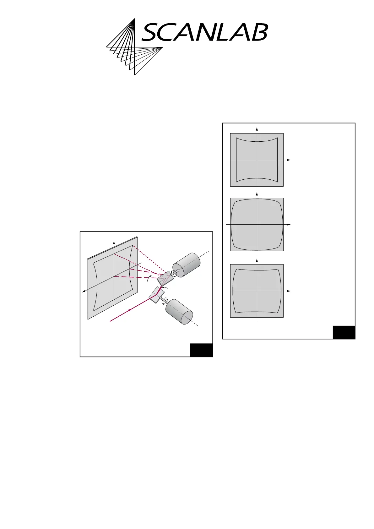
The deflection of a laser beam with a two-mirror
system results in three effects:
(1) The arrangement of the mirrors leads to a certain
distortion of the Image Field
(1)
, see Figure 49.
(2) The distance in the Image Field is not
proportional to the scan angle itself, but to the
tangent of the scan angle. Therefore, the
mark speed of the laser focus in the Image Field is
not proportional to the angular velocity of the
corresponding scanner.
(3) If an ordinary lens is used for focusing the laser
beam, the focus lies on a sphere. In a flat Image
Field plane, a varying spot size results.
By focusing the deflected laser beam with an F-Theta
objective, effect 2 and effect 3 can be avoided.
However, this causes a barrel-shaped distortion of the
Image Field, see Figure 50.
(1) Cause: the distance between mirror 1 and the Image
Field depends on the size of the scan angles of mirror 1
and mirror 2. A larger scan angle leads to a longer
distance.
49
Image field distortion when deflecting a beam in a
two-mirror deflection system.
ϕ
2
ϕ
1
X
Y
Beam in
Mirror 1
Mirror 2
Image field
plane
Galvanometer scanner
2
Galvanometer scanner
1
50
Image field distortion caused by the arrangement of the
mirrors and by the F-Theta objective.
Pillow-shaped
Image Field
distortion. Caused
by the arrangement
of the mirrors.
Barrel-shaped
Image Field
distortion. Caused
by the F-Theta
objective.
Resulting
barrel-pillow-shaped
Image Field
distortion.