RTC6 boards
Doc. Rev. 1.0.21 en-US
2 Product Overview
43
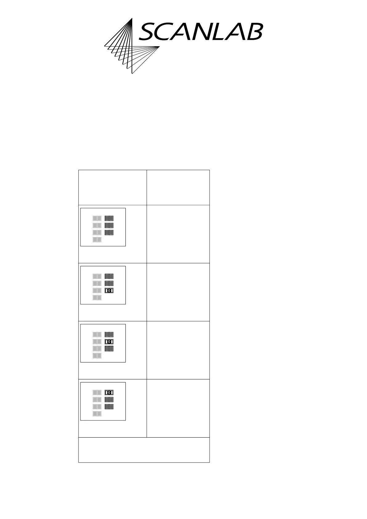
2.7.3 Solder Jumper Field C –
Configuring Pin (15) of
EXTENSION 2 Socket Connector
The solder jumper field C is located on the lower side
of the RTC6 PCIe Board, see Figure 6.
It serves to configure the signal at pin (15) of the
EXTENSION 2 socket connector, see the following
table.
See also “Configuration by Solder Jumpers”, page 80.
Notes
• Configurations of solder jumper field C and
solder jumper field B are independent from each
other.
• On RTC6 Ethernet Boards, the printed label of
solder jumper field B is ’Pin15’. This has been
chosen deliberately in order to keep consistency
with already existing RTC boards. Even though
with RTC6 Ethernet Boards pin (08) of the EXT. 2
socket connector, see Chapter 16.2.12 ”EXT. 2
Socket Connector”, page 891, is actually
configured.
Allowed
jumper setting
Output at the
EXTENSION 2
socket connector
pin (15)
No signal.
GROUND
(low level).
+5 V
(high level).
DATA 7
(a)
.
(a) Synonym: Data Bit #7. MSB of the 8-bit output value.
*
Caution: make sure that only one position is closed
in this solder jumper field. Other combinations are
not allowed and cause damage to the board!
GND
+5V
Data7
Pin15Pin17
Latch
GND
+5V
Data7
open
open
open
GND
+5V
Data7
Pin15Pin17
Latch
GND
+5V
Data7
open
open
closed*
GND
+5V
Data7
Pin15Pin17
Latch
GND
+5V
Data7
open
closed*
open
GND
+5V
Data7
Pin15Pin17
Latch
GND
+5V
Data7
closed*
open
open