RTC6 boards
Doc. Rev. 1.0.21 en-US
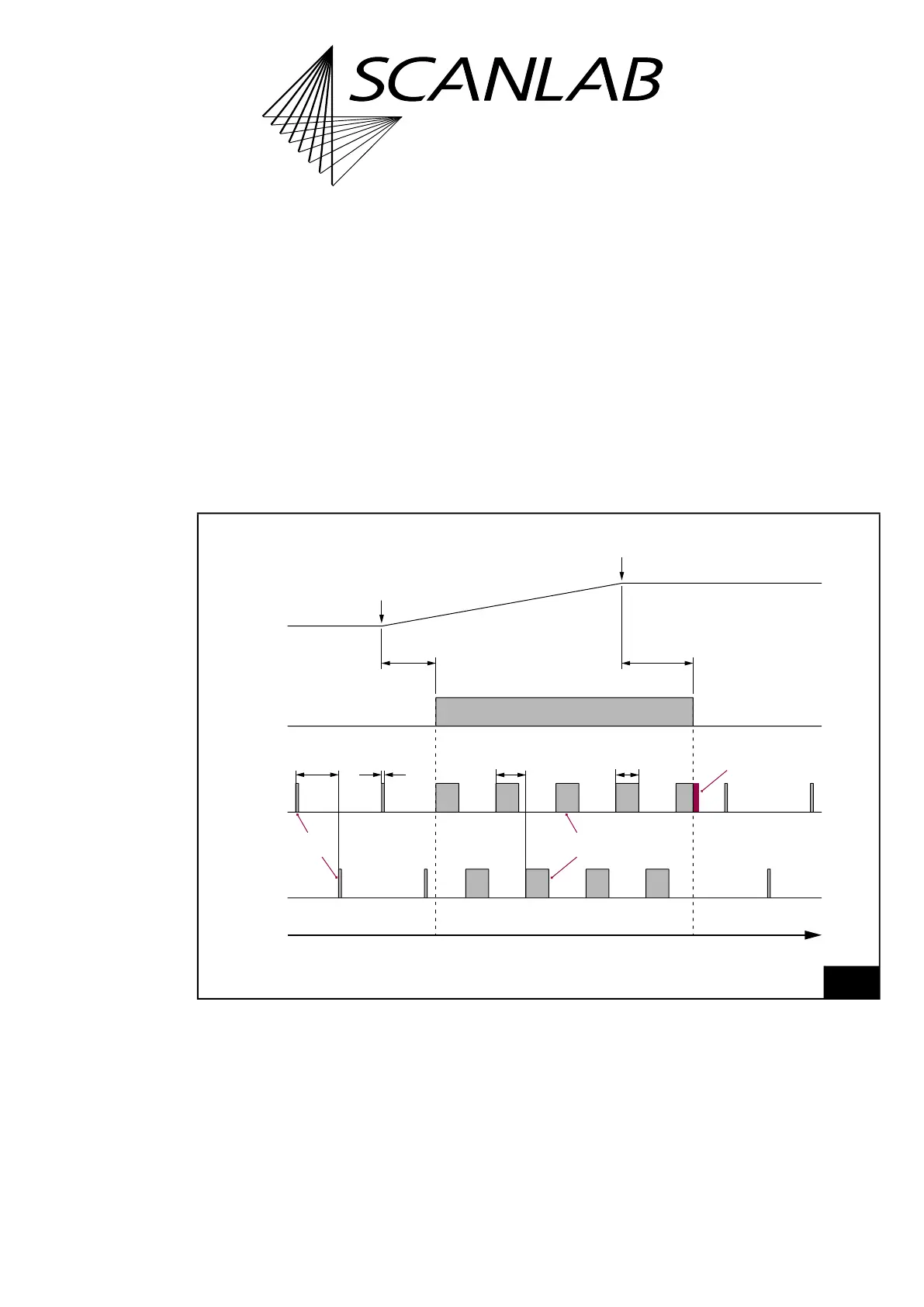
7 Basic Functions for Scan Head Control and Laser Control
188
7.4.3 CO
2
Mode
set_laser_mode
(0)
sets the CO
2
Mode
(“Laser Mode 0”).
The timing diagram, see Figure 52, shows the
corresponding signals using the example of an
isolated mark command.
For “laser active” operation:
• The LASERON signal is switched on
• 2 alternating modulation signals are outputted at
the LASER1 and LASER2 output port. Their
pulse length and period duration can be defined
by set_laser_pulses, set_laser_pulses_ctrl or
set_laser_timing.
For “laser standby” operation:
• The LASERON signal is switched off
• Alternating standby pulses are outputted at the
LASER1 and LASER2 output port.
Their pulse length and period duration can be
defined by set_standby or set_standby_list.
52
Timing diagram of the signals in CO
2
Mode (with active-HIGH Laser Control Signals).
Example: isolated mark command.
t
“Laser active”“Laser standby” “Laser standby”
set_laser_control Bit #0 = 1
LaserOn
Delay
LaserOff
Delay
LASER1
LASER2
LASERON
Pulse completion
Puls length
Half
period duration
Modulation
signals
Puls length
Half
period duration
Standby
pulses
Start of
mark command
End of
mark command
Mark Command
Output
CO
2
Mode