RTC6 boards
Doc. Rev. 1.0.21 en-US
7 Basic Functions for Scan Head Control and Laser Control
196
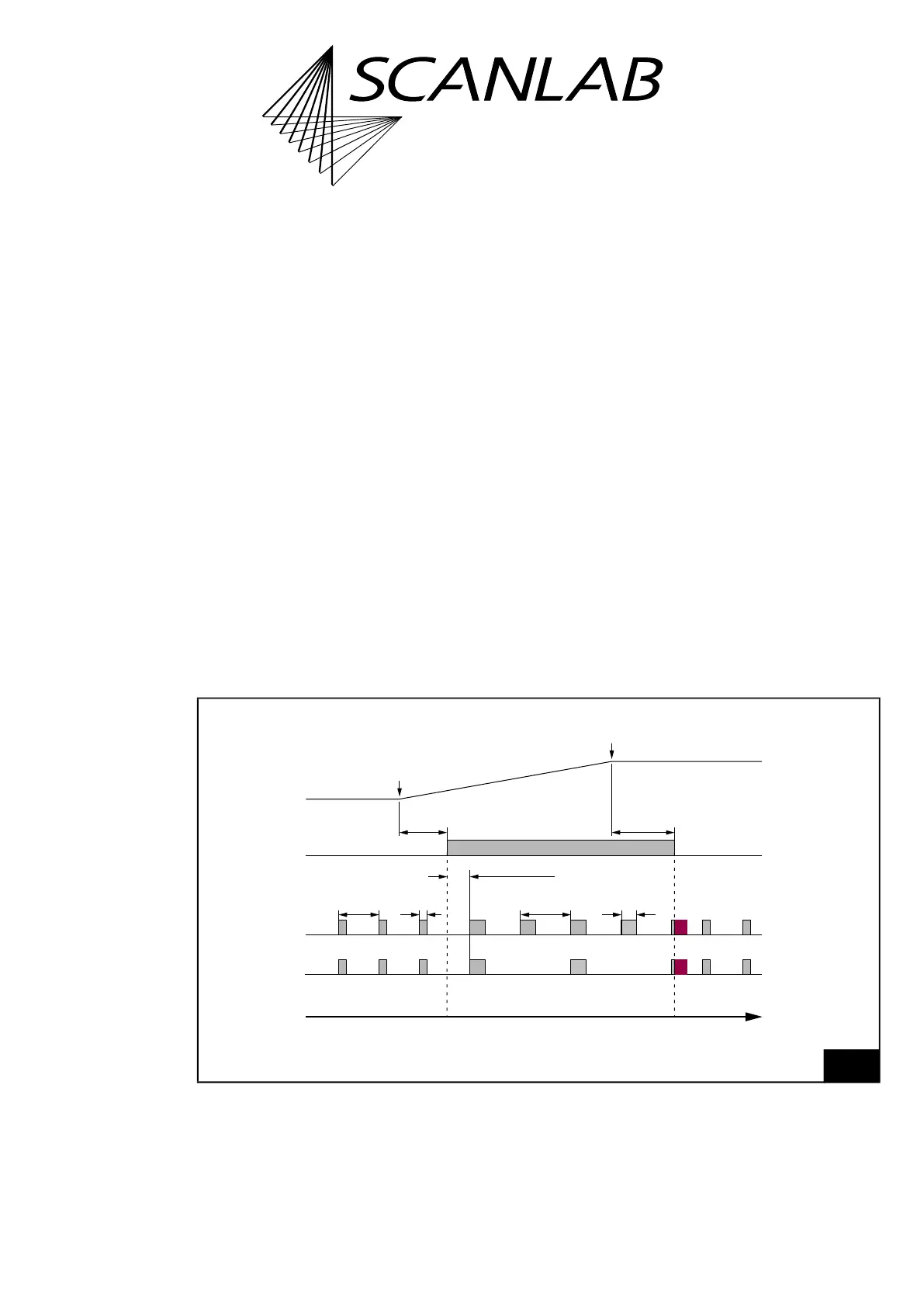
7.4.8 Pulse Picking Laser Mode
By set_pulse_picking or set_pulse_picking_list, the
Pulse Picking Laser Mode can be set. The laser control
timing diagram in Figure 56 shows the
corresponding signals.
For “laser active” operation:
• The LASERON signal is switched on
• A modulation signal is provided at the LASER1
output with pulse length and period duration
that can be defined by set_laser_pulses,
set_laser_pulses_ctrl or set_laser_timing
• At the LASER2 output every
No
th
pulse of the
signals is outputted at the LASER1 output (in
phase).
No
is set with set_pulse_picking or
set_pulse_picking_list
For “laser standby” operation:
• The LASERON signal is switched off
• Standby pulses are provided in phase at the
LASER1 and LASER2 outputs with pulse lengths
and periods that can be defined by set_standby
or set_standby_list. Standby pulses cannot be
“pulse-picked”.
Notes
• With set_laser_control( Bit #7 = 1 ) the
Pulse Picking signal at LASER2 can be set to a
constant length independent of the
LASER1 signal, which is set with
set_pulse_picking_length.
• set_pulse_picking and set_pulse_picking_list
overwrite a laser mode previously set with
set_laser_mode. Vice versa, set_laser_mode
switches off the Pulse Picking Laser Mode.
• For the LASER1 signals, half the period duration
must be specified.
• A Q-Switch delay is effective, see also Section
”Differences Between the YAG Modes”,
page 190.
• A FirstPulseKiller signal is not outputted.
• The setting sequence of the LASER1 signals and
the Pulse Picking Laser Mode is irrelevant.
56
Timing diagram of the signals in Pulse Picking Laser Mode (with active-HIGH Laser Control Signals and
No
= 2).
Example: isolated mark command.
t
LASER1
LASER2
(No = 2)
LASERON
“Laser active”“Laser standby” “Laser standby”
LaserOn
Delay
LaserOff
Delay
Q-Switch
Period
Q-Switch
Pulse Length
Q-Switch Delay
Standby
Pulse Length
Standby
Period
End of
mark command
Start of
mark command
Mark Command
Output
Pulse Picking Laser Mode