RTC6 boards
Doc. Rev. 1.0.21 en-US
4 RTC6 PCIe Board – Layout and Interfaces
69
4.5.2 XY2-100 Converter (Accessory)
The SCANLAB XY2-100 Converter (Accessory)
(#125377) converts:
• SL2-100 protocol-compliant control signals
(20 bit) to XY2-100 protocol-compliant control
signals (16 bit)
• Scan system XY2-100 protocol-compliant status
signals to SL2-100 protocol-compliant status
signals, see also Chapter 7.3.7 ”Status
Monitoring and Diagnostics”, page 183
When controlling scan systems, the
XY2-100 Converter (Accessory) introduces a 10 µs
signal propagation delay. To compensate for this, the
LaserOn Delay and LaserOff Delay must be increased
by 10 µs each, see set_laser_delays.
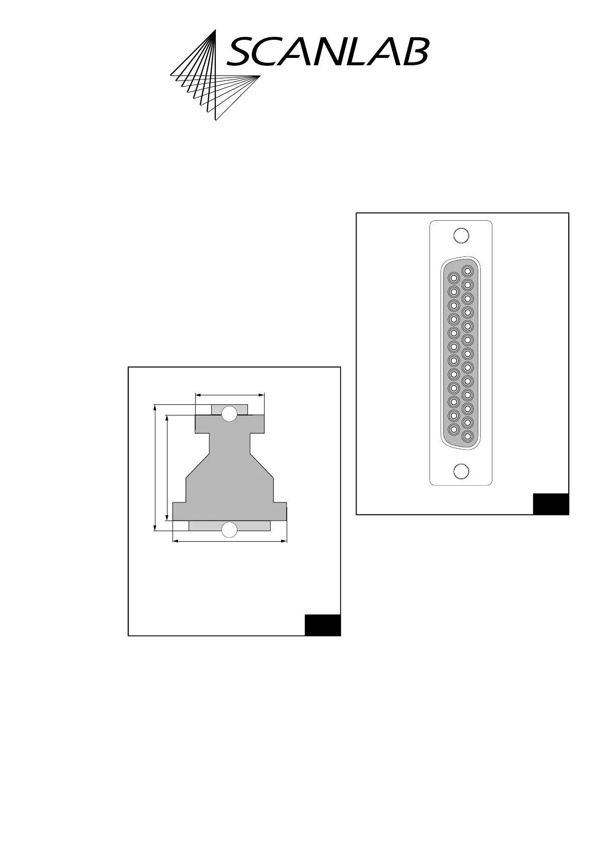
The dimensions are shown in Figure 12.
The 9-pin D-SUB (male) plug of the
XY2-100 Converter (Accessory) should be directly
plugged into the SCANHEAD connector of the
RTC6 PCIe Board or, (by a short-as-possible 1:1 cable)
connected to the corresponding 2. SCANHEAD
connector pins of the RTC6 PCIe Board. For the
pin-out, see Figure 10 and Figure 11.
The 25-pin D-SUB connector (female) of the
XY2-100 Converter (Accessory) is compatible with
scan heads that provide an XY2-100 standard
interface.
The pin-out is shown in Figure 13.
The data channels CHAN1 and CHAN2 transmit
control values to the scan head. The SYNC and CLOCK
channels transmit synchronization and clock signals
to the scan system.
The STATUS channel (and, if appropriate, the
STATUS1 channel) receives XY2-100-compliant status
signals returned by the scan system.
12
XY2-100 Converter (Accessory): dimensions.
2
1
52 mm
62 mm
56.5 mm
34.5 mm
Thickness
12.5 mm
Legend
1. 9-pin D-SUB plug, male
2. 25-pin D-SUB connector, female
13
XY2-100 Converter (Accessory): pin-out of the 25-pin
D-SUB connector (female).
* For iDRIVE scan systems (see Glossary entry on page 27),
the STATUS± channel is the status channel of axis 2 (x axis;
this channel is then also called STATUS2±) and the
STATUS1± channel is the status channel of axis 1 (y axis).
For other scan systems, the STATUS1± channel can not be
used: “DO NOT CONNECT”.
* STATUS+ (19)
(07) DO NOT CONNECT
DO NOT CONNECT (18)
(06) STATUS– *
CHAN2+ (17)
(05) DO NOT CONNECT
CHAN1+ (16)
(04) CHAN2–
SYNC+ (15)
(03) CHAN1–
CLOCK+ (14)
(02) SYNC–
(01) CLOCK–
(13) DO NOT CONNECT
(12) DO NOT CONNECT
(11) DO NOT CONNECT
(10) DO NOT CONNECT
(09) DO NOT CONNECT
(08) STATUS1– *
DO NOT CONNECT (25)
DO NOT CONNECT (24)
DO NOT CONNECT (23)
DO NOT CONNECT (22)
* STATUS1+ (21)
DO NOT CONNECT (20)