RTC6 boards
Doc. Rev. 1.0.21 en-US
4 RTC6 PCIe Board – Layout and Interfaces
70
If cables longer than 20 m (not recommended) are
used for data transmission between the
XY2-100 Converter (Accessory) and the scan system,
then the synchronization of bidirectional
communication between the scan system and the
RTC6 PCIe Board should be configured.
This can be accomplished by two solder jumpers in
the XY2-100 Converter (Accessory).
To do so, carefully open the housing of the
XY2-100 Converter (Accessory) by its 4 clip latches
(1)
.
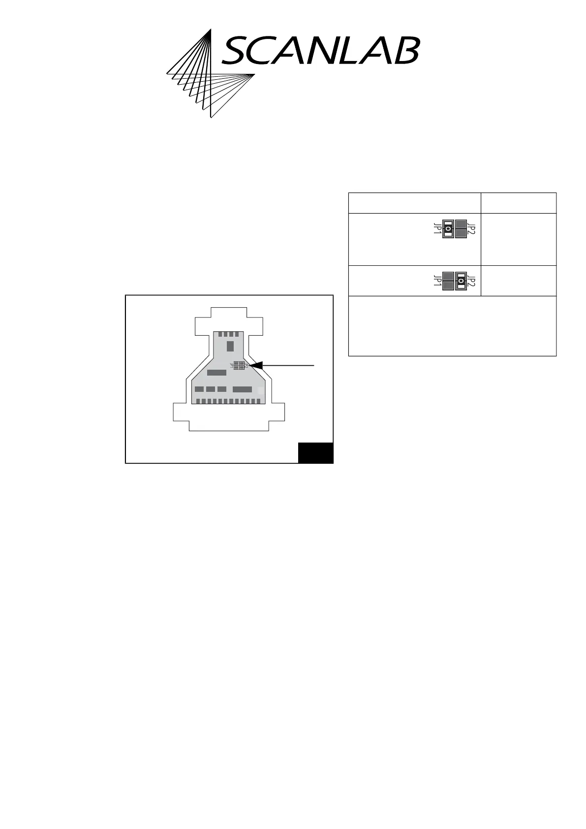
The solder jumpers JP1 and JP2 are on the PCB, see
arrow in Figure 14.
The following table shows the possible jumper
settings and the corresponding cable lengths. Other
jumper settings are not allowed. Cable lengths above
20 m are not recommended.
Notes
• Observe the note on get_head_status, page 213.
(1) For example, using a slotted screwdriver.
14
XY2-100 Converter (Accessory): positions of solder jumpers
JP1 and JP2 on the PCB.
Jumper setting Cable length*
JP1 closed
JP2 open
(default
configuration)
0 m to 20 m
JP1 open
JP2 closed
20 m to 40 m
* The cable length range mentioned here for the
respective jumper configuration depends on the used
cable type and may differ from the values mentioned
above. Cable lengths over 20 m are generally not
recommended (and require extensive checks by users
prior to productive use).