RTC6 boards
Doc. Rev. 1.0.21 en-US
4 RTC6 PCIe Board – Layout and Interfaces
80
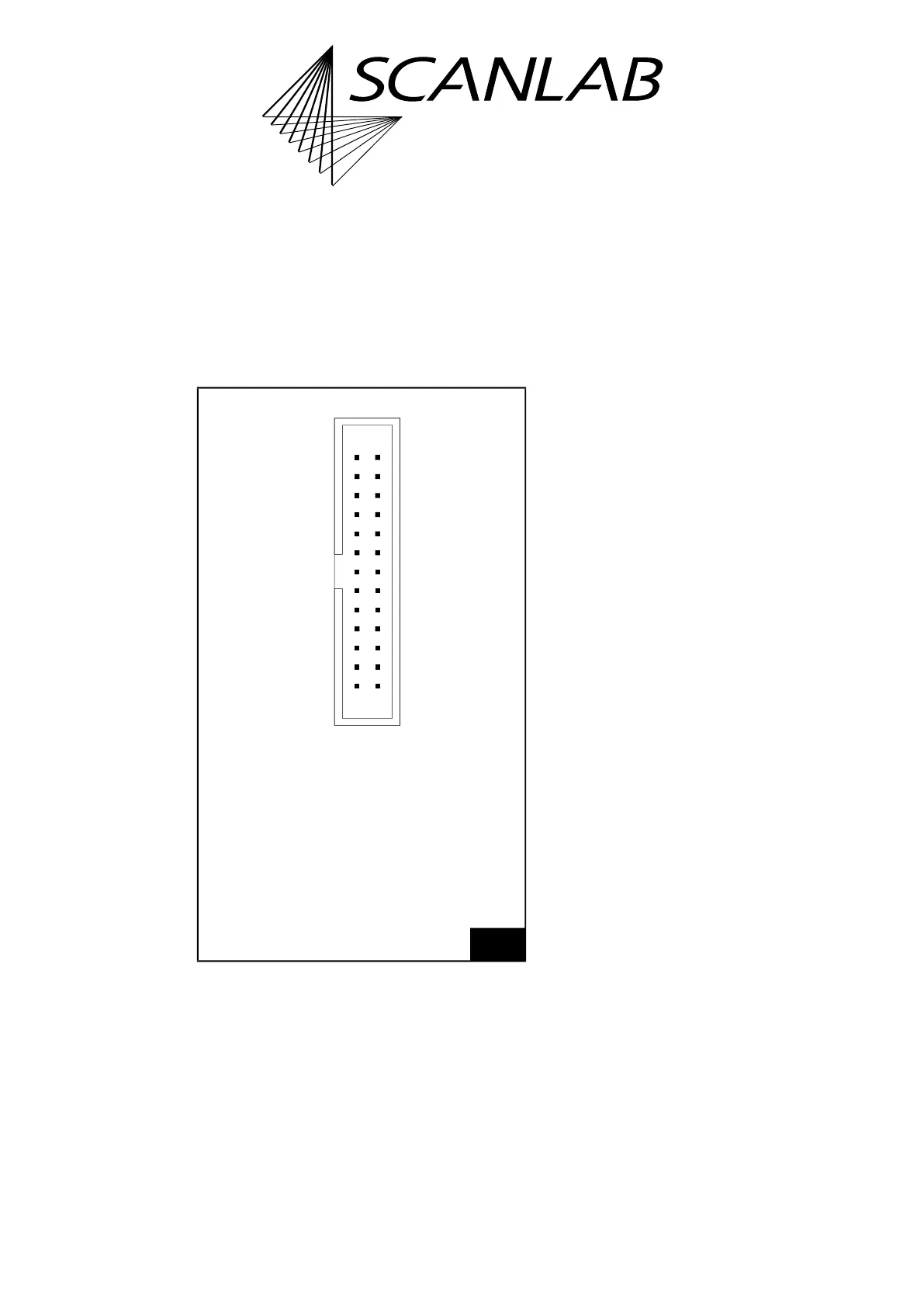
4.6.3 EXTENSION 2 Socket Connector
The EXTENSION 2 socket connector
(1)(2)
has 26 pins.
It is located on the upper side of the RTC6 PCIe Board,
see Figure 5.
It provides a buffered 8-bit digital output port:
DATA0…DATA7.
The pin-out is shown in Figure 24.
Notes
• Pin (15) and pin (17) are configurable by solder
jumpers.
Configuration by Solder Jumpers
Pin (15) is configured by the solder jumper field C,
see Chapter 2.7.3 ”Solder Jumper Field C –
Configuring Pin (15) of EXTENSION 2 Socket
Connector”, page 43.
Pin (17) is configured by solder jumper field B, see
Chapter 2.7.2 ”Solder Jumper Field B – Configuring
Pin (17) of EXTENSION 2 Socket Connector”,
page 42.
Notes
• If the DATA7 bit is assigned to pin (15), then the
full 8-bit output value is available at the
output port (at the odd numbered pins of the
EXTENSION 2 socket connector,
pin (01)…pin (15)).
• If pin (15) is set to +5 V (HIGH level), then the
output values have an offset of 128. That is, the
output values are between 128…255.
• If pin (15) is set to GND (LOW level), then the
possible output values are 0…127.
• The DATA7 bit can be used for other purposes by
assigning it to pin (17).
(1) On the RTC4, the functional corresponding
socket connector is labeled LASER EXTENSION.
(2) RTC6 Ethernet Boards do not provide Laser Control
Signals (LASER1 and LASER2) at their (10-pin) EXT. 2
socket connectors.
24
EXTENSION 2 socket connector: pin-out. The pitch of the
pins is 2.54 mm.
2625
21
(LSB) DATA0 (01) (02) GND
DATA1 (03) (04) NOT CONNECTED
DATA2 (05) (06) +5 V
DATA3 (07) (08) NOT CONNECTED
DATA4 (09) (10) NOT CONNECTED
DATA5 (11) (12) NOT CONNECTED
DATA6 (13) (14) NOT CONNECTED
* (15) (16) NOT CONNECTED
** (17) (18) +5 V
LASER2 (19) (20)
(21)
(20)
(21) (22) LASER1
GND2 (23) (24) NOT CONNECTED
+5 V (25) (26) LASERON
** Depends on solder jumper position:
+5V or DATA7 or GND or LATCH.
* Depends on solder jumper position:
+5V or DATA7 or GND.
Identical in construction to Würth 61202621621.