RTC6 boards
Doc. Rev. 1.0.21 en-US
7 Basic Functions for Scan Head Control and Laser Control
150
Polygon Delay
The Polygon Delay is specified by
set_scanner_delays with the
Polygon
parameter.
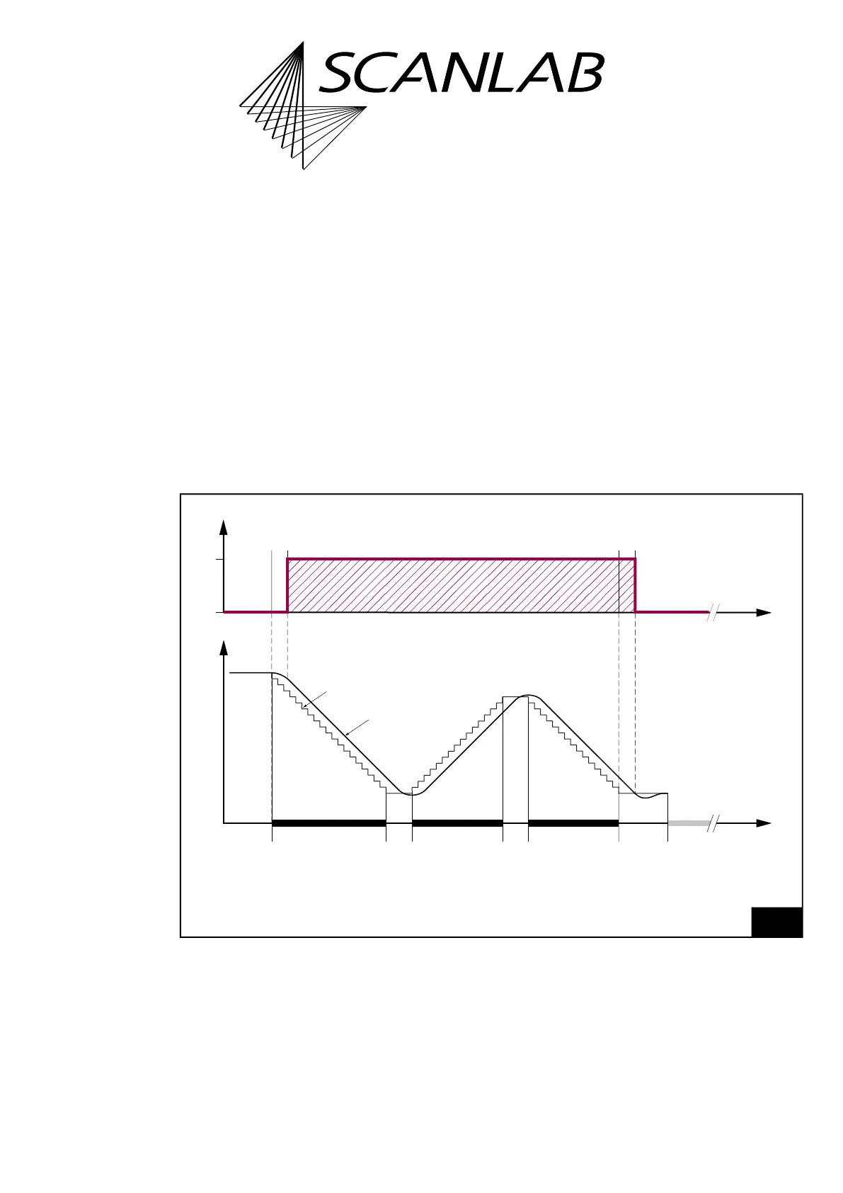
A typical course for a series of Mark Commands
(“Polyline”) where Polygon Delays (instead of
Mark Delays) are inserted between the individual
Mark Command is shown in Figure 38.
Short list commands do not interrupt a Polyline.
If the (usually smaller) angles between the markings
vary only slightly usually a Polygon Delay value can be
specified that is smaller than the Mark Delay value.
If, on the other hand, the angles vary significantly,
then a “Variable Polygon Delay” is recommended, see
Section ”Variable Polygon Delays”, page 151.
38
Scan head control and laser control timing during a Polyline with a constant Polygon Delay.
Position
…
0
1
Laser
Time
Jump
command
etc.
Mark
Delay
Last Mark
command
in this
polyline
Polygon
Delay
Mark
command
Polygon
Delay
Mark
command
Real Position
Set Position
LaserOff
Delay
LaserOn
Delay
Time