RTC6 boards
Doc. Rev. 1.0.21 en-US
9 Programming Peripheral Interfaces
289
9.3 Control by External Signals
The previously described input and output of
peripheral signals can be synchronized with
scan system control and laser control, as follows:
• The related list commands can be inserted in
command lists at appropriate locations.
• Execution of related control commands can be
made dependent on the current status of list
execution. For this, the list status can be
requested by read_status, see Chapter 6.4.2 ”List
Status”, page 107 and the list execution status by
get_status, see Chapter 6.4.3 ”List Execution
Status”, page 108.
• In addition, the BUSY list execution status List
Execution Status is provided by the BUSY OUT
signal:
– at the LASER Connector,
see Section ”BUSY List Execution Status”,
page 74
– at the EXTENSION 1 socket connector,
see Section ”BUSY List Execution Status”,
page 79
– at the MARKING ON THE FLY socket connector,
see Section ”BUSY List Execution Status”,
page 82
Moreover, the RTC6 PCIe Board provides commands
and interfaces (described in the following sections)
that allow external control signals (for example, from
a light-barrier or from an encoder) to directly control
and synchronize execution of command lists or
individual commands (including the output of
peripheral signals).
Moreover, the RTC6 PCIe Board provides interfaces to
control and synchronize list execution directly with
external signals.
9.3.1 Starting and Stopping Lists by
External Control Signals
and Master/Slave
Synchronization
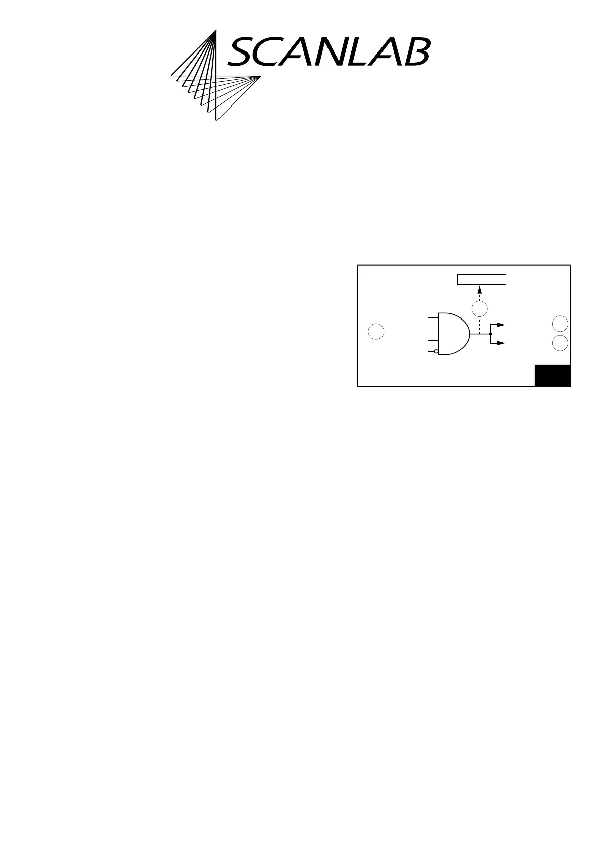
External Stop
By a signal at the input ports /STOP, /STOP2 or /Slave
STOP, or by simulate_ext_stop, an External Stop can
be initiated, see (1) and (3) in Figure 68.
This:
• immediately cancels the currently executed list
• switches off the Signals for “Laser Active”
Operation (but does not deactivate them)
Like after calling stop_execution (internal stop), the
following output ports are then set to the previously
defined (by set_port_default) stop-case values given
these have not been defined as
“–1”:
• the 16-bit digital output port of the EXTENSION 1
socket connector
• the 8-bit digital output port (DATA0 to DATA7) of
the EXTENSION 2 socket connector
• the 2-bit digital output port
• the two 12-bit analog output ports
(ANALOG OUT1 and ANALOG OUT2) of the
LASER Connector
68
External Stop. See text for description.
4
3
2
1
/external STOP
/Master-STOP
ext-stop status
AND
simulate_ext_stop
/Slave-STOP
/STOP2
/STOP