RTC6 boards
Doc. Rev. 1.0.21 en-US
7 Basic Functions for Scan Head Control and Laser Control
151
Variable Polygon Delays
By setting the
VarPoly
value > 0 (at set_delay_mode
or set_delay_mode_list) it is enabled:
• “Variable Polygon Delays” mode
Then, the RTC6 PCIe Board calculates the “Variable
Polygon Delay“ v_delay() for every Polyline corner
according to:
v_delay() = scale() × polygon_delay
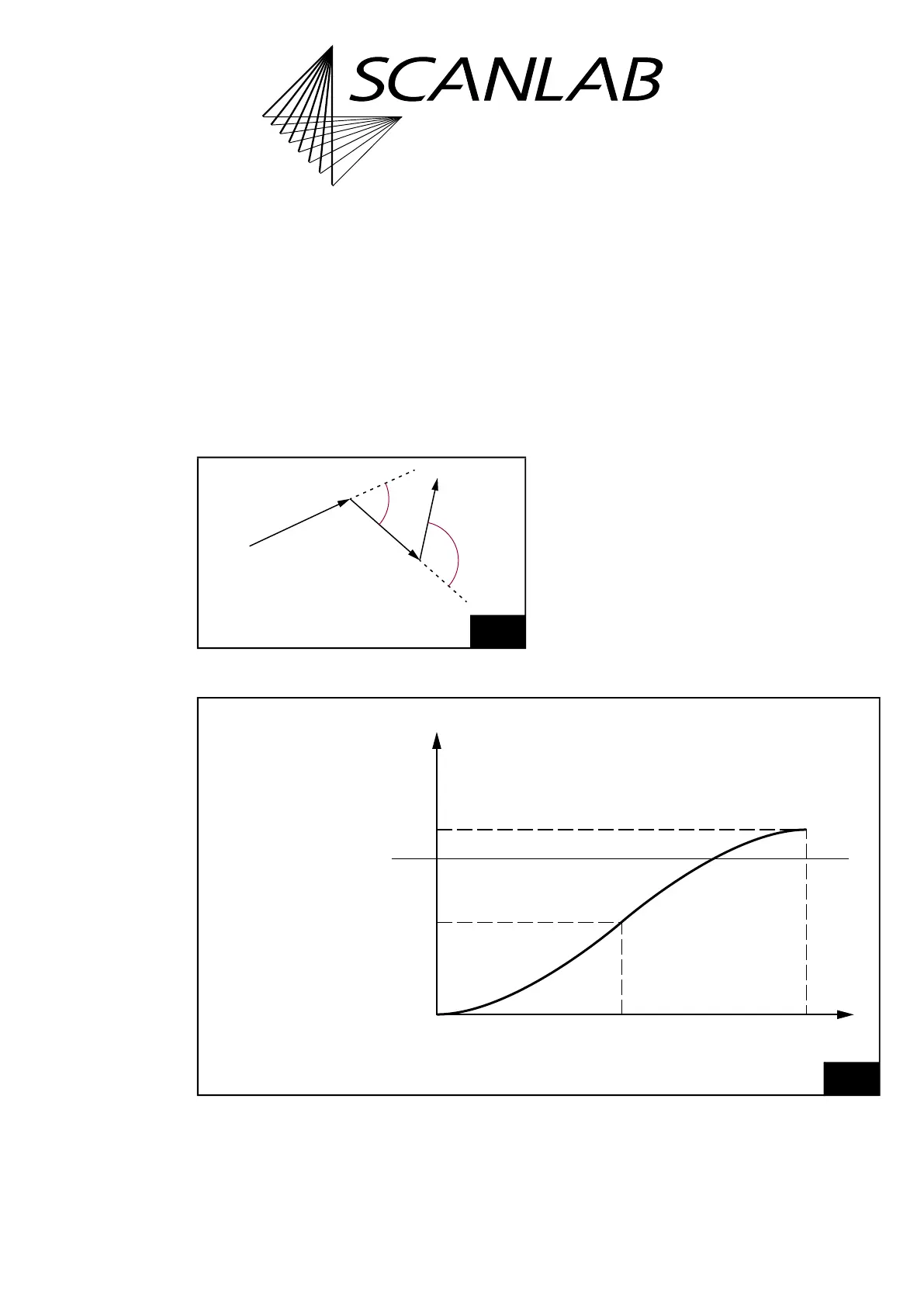
For the definition of the angle using the example of
mark vectors, see Figure 39.
For circular arcs and ellipses, analogously the
tangents at the connection point are relevant.
scale() is a scaling function for the
Polygon
value
from set_scanner_delays (constraint
0 scale() 2), see Figure 40. The default scaling
function after load_program_file is
scale() = 1 – cos(). It can be replaced by a
user-defined scaling function, see Section ”User-
defined “Variable Polygon Delays””, page 153.
39
Variable Polygon Delays. Definition of the angle .
ϕ
2
Mark
Mark
ϕ
1
Mark
Angles between the
vectors of a Polyline
40
Variable Polygon Delays. Variation of the Polygon Delay (default scaling function after load_program_file).
1 – cos (ϕ)
ϕ
180°
90°0°
0
1
2
scale (ϕ)
EdgeLevel
Polygon Delay =
scale() ×
Polygon
value
from set_scanner_delays.
Maximum