RTC6 boards
Doc. Rev. 1.0.21 en-US
7 Basic Functions for Scan Head Control and Laser Control
194
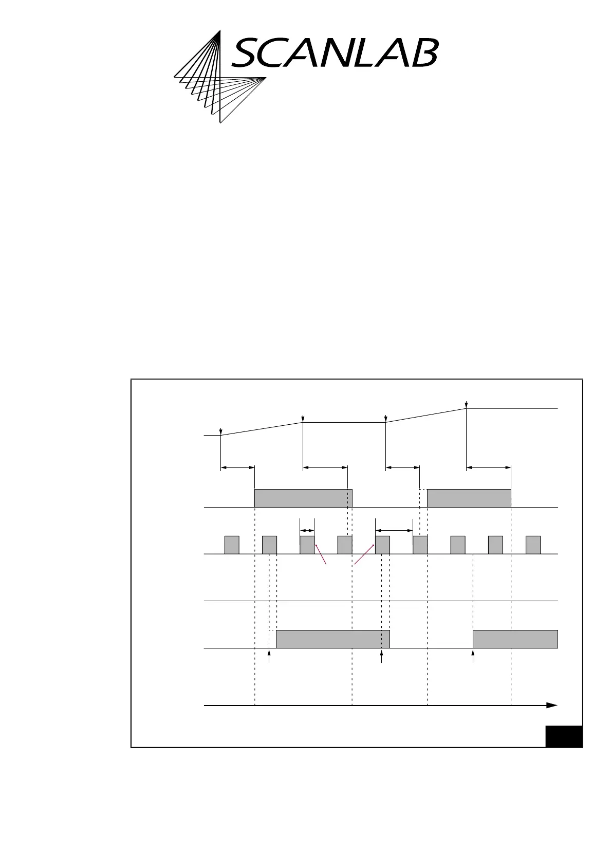
7.4.6 Laser Mode 6
set_laser_mode(6)
sets the Laser Mode 6.
Laser Mode 6 is like Laser Mode 4 and is provided for
those free-running lasers whose gate signals
(LASERON) must not be changed during the duration
of a pulse.
The timing diagram, see Figure 55, shows the
corresponding signals using the example of an
isolated mark command.
Laser Mode 6 signals and Laser Mode 4 signals are
the same (see also Notes there, page 193) with the
following exception:
• As long as a standby pulse is active, switching of
the LASERON signal is delayed accordingly.
LASERON switches 5/64 µs after the end of the
standby pulse.
Notes
• No LASER2 signal is outputted.
• The delay of the switching time when a standby
pulse is still active is also valid for switching the
output values at the 2-bit digital output port
(DIGITAL OUT1 and DIGITAL OUT2) by
set_laser_pin_out, set_laser_pin_out_list or
write_port_list, see Figure 55.
55
Timing diagram of the signals in Laser Mode 6 (with active-HIGH Laser Control Signals).
Example: isolated mark commands.
t
“Laser standby”“Laser active”“Laser standby”“Laser active””Laser standby”
set_laser_pin_outset_laser_pin_outset_laser_pin_out
LaserOff
Delay
LaserOn
Delay
LaserOff
Delay
LaserOn
Delay
DIGITAL OUT1
DIGITAL OUT2
LASER2
LASER1
LASERON
End of
mark command 2
Start of
mark command 2
End of
mark command 1
Start of
mark command 1
Mark Command
Output
Standby
pulses
Puls length
2×Half period
duration
Laser Mode 6