RTC6 boards
Doc. Rev. 1.0.21 en-US
7 Basic Functions for Scan Head Control and Laser Control
193
7.4.5 Laser Mode 4
set_laser_mode(4)
sets the Laser Mode 4.
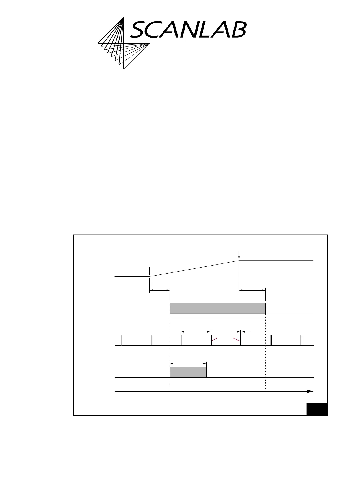
The timing diagram, see Figure 54, shows the
corresponding signals using the example of an
isolated mark command.
At LASER1 output port, for “laser active” operation
as well as for “laser standby” operation standby
pulses are outputted continuously.
Pulse length and period duration of the standby
pulses can be set by set_standby or
set_standby_list.
For “laser active” operation:
• The LASERON signal is switched on
• A programmable FirstPulseKiller signal is
outputted at the LASER2 output
For “laser standby” operation:
• the LASERON signal is switched off
• and the LASER2 signal is switched off
Notes
• LASER1 signals are
– activated by:
HalfPeriod
0 and
PulseLength
0
– deactivated by:
HalfPeriod
= 0 and/or
PulseLength
= 0 (default setting after
load_program_file)
• The FirstPulseKiller signal is started together with
the LASERON signal automatically. The length of
the FirstPulseKiller signal is set by
set_firstpulse_killer or set_firstpulse_killer_list.
• Laser Mode 4 is used for some fiber lasers.
54
Timing diagram of the signals in Laser Mode 4 (with active-HIGH Laser Control Signals).
Example: isolated mark command.
t
“Laser active”“Laser standby” “Laser standby”
LaserOn
Delay
LaserOff
Delay
(FirstPulseKiller)
LASER2
LASER1
LASERON
FirstPulseKiller
length
Puls length
2×Half period
duration
Start of
mark command
End of
mark command
Mark Command
Output
Standby
pulses
Laser Mode 4