RTC6 boards
Doc. Rev. 1.0.21 en-US
8 Advanced Functions for Scan Head Control and Laser Control
263
8.7 Pixel Output Mode
The Vector Commands described in Chapter 7.1
”Marking Dots, Lines and Arcs”, page 136 are
intended for scanning vector based images.
Furthermore, the RTC6 PCIe Board allows marking
pixel images (bitmaps). With suitably adjusted lasers,
black-and-white images or greyscale images can be
obtained. Raster and vector based images can be
combined as desired.
8.7.1 Principle of Operation
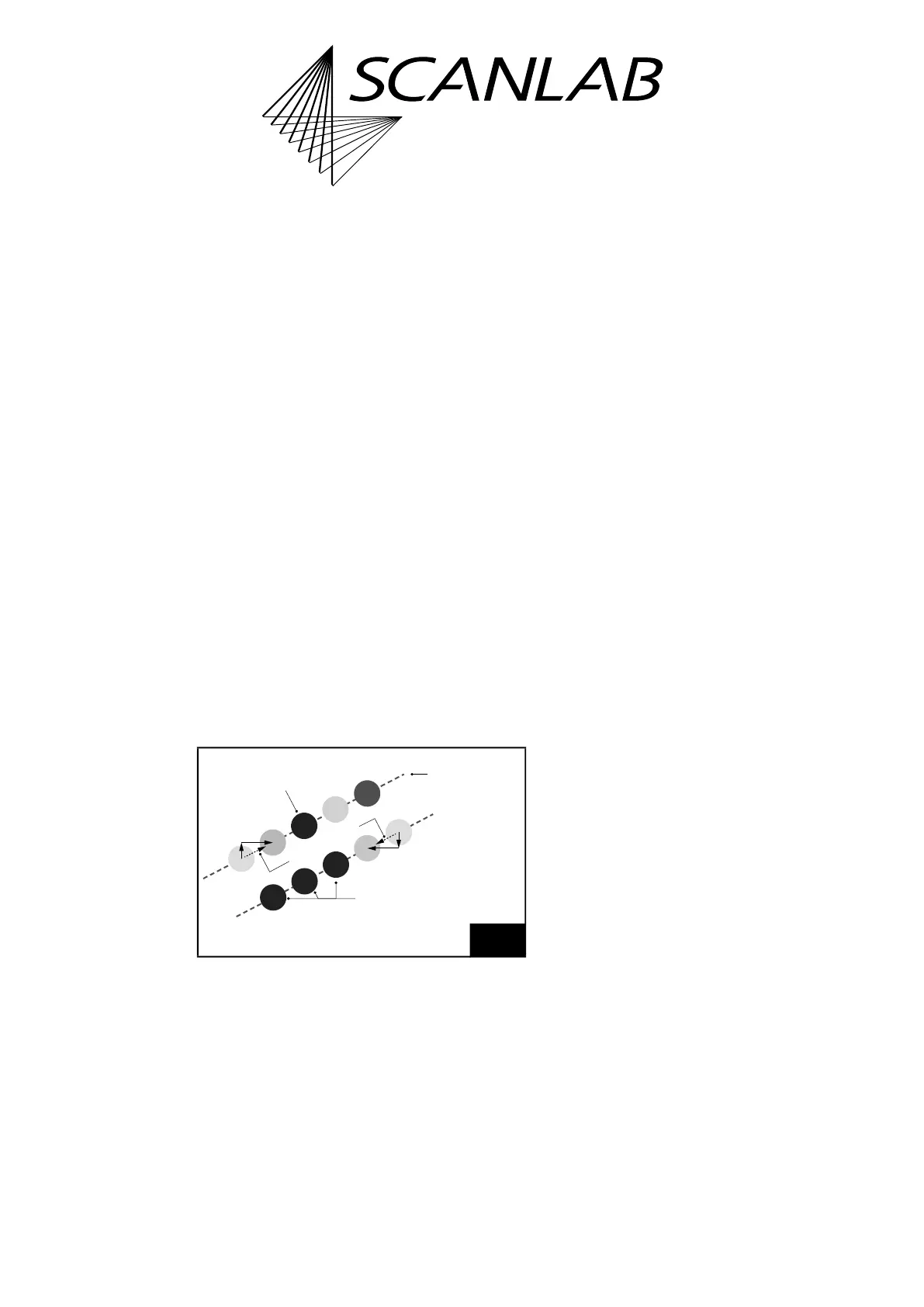
Pixel images are created image line by image line, see
Figure 64. Each line consists of a number of
equidistant pixels. A line is generated in a single pass.
During this pass, the laser focus moves – as with a
normal [*]mark[*] Command – at an (approximately)
constant velocity along the entire image line (the
motion is split-up into Microsteps). The individual
pixels are marked in passing: each pixel gets a laser
pulse assigned at the appropriate location. By varying
the laser energy from pixel to pixel, greyscale images
(including black & white images) are produced.
Different output ports can be used to control the
laser depending on mode and pixel output frequency,
see command descriptions.
• By set_pixel_line, a single line is configured:
– The spatial distance between the individual
pixels with the parameters
dX
,
dY
(with
set_pixel_line_3d additionally
dZ
)
– The temporal distance between the individual
pixels with the parameter
HalfPeriod
– The parameter
Channel
is extended compared
to the RTC5 to Channel= Mode + Port, where
now the (pixel) mode is defined via the value
Mode and the Output Port is defined via the
value Port, see Table 5 and 6
Notes
• The Pixel Output Mode can be combined with
Processing-on-the-fly, see Chapter 8.6
”Processing-on-the-fly”, page 242.
• The Pixel Output Mode should not be used in
conjunction with “Automatic Laser Control“ (see
Chapter 7.4.9 ”“Automatic Laser Control“”,
page 197), if there is a readjustment of the port
output, pulse length (
PulseLength
) or output
period (
HalfPeriod
) of the Laser Control Signals
LASER1 and LASER2.
• The Pixel Output Mode cannot be combined with
Sky Writing.
(1)
• The Pixel Output Mode cannot be combined with
Wobbel Mode.
8.7.2 RTC6 Commands
Before writing an image line, a jump to the beginning
of the line should be executed by a Jump Command.
At the beginning of each image line, the Pixel Output
Mode is activated by set_pixel_line or
set_pixel_line_3d. The pixel distance and pixel
output period (and, resultingly, the speed at which
the image line is traversed) are simultaneously set as
well.
64
An individual set_pixel_line is required for each image line.
The individual pixels of this line are then defined by
successive set_pixel/set_n_pixel.
–dY
–dX
+dY
+dX
n pixel by
1 set_n_pixel (n=3)
Scan direction
Each line needs
1 set_pixel_line
1 pixel by
1 set_pixel
(1) However, the Pixel Output Mode can also be executed
so that automatically generated (Sky Writing Mode 1-
like) pre and post movements are included. This makes
it easier to output pixel images with accurate
positioning, see Chapter 8.7.4 ”Synchronization”,
page 268.