RTC6 boards
Doc. Rev. 1.0.21 en-US
8 Advanced Functions for Scan Head Control and Laser Control
232
8.4 Wobbel Mode
The Wobbel Mode allows varying the line width for
laser marking.
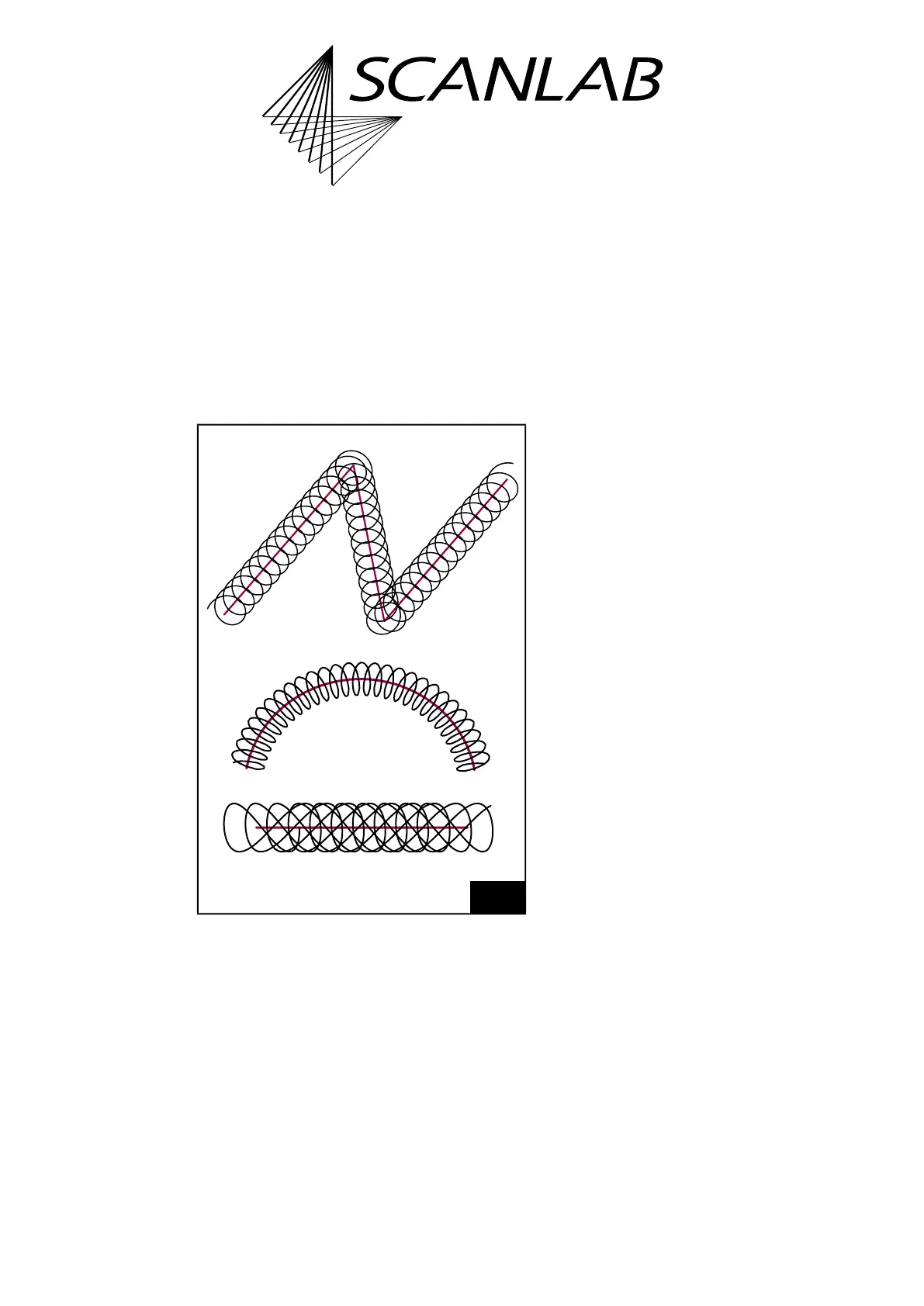
For this purpose, for example, an ellipse-shaped
motion is added to the regular, linear movement of
the output position. This results in a spiral movement
of the laser focus in the Image Field, see Figure 62.
Alternatively, the motion can be combined with a
horizontal or vertical figure-of-8.
A broadening of the original line is obtained by
choosing suitable values for the transverse and
longitudinal amplitudes and the frequency of the
wobbel movement. With figure-of-8s, broader mid-
line processing can be achieved by appropriate
parameter values. If the specified transverse and
longitudinal amplitudes are identical, then the
wobbel shape remains stationary in space; otherwise
the orientation of the wobbel shape follows the
current direction of motion. If there is no direction of
movement, no wobbel movement is performed.
During Processing-on-the-fly correction by the
McBSP interface or encoder interface where the
scan head only compensates differences between
actual external movements and intended total
motion, see Chapter 8.6.2 ”Compensating Linear
Movements”, page 243, a slight jitter in the direction
of galvanometer scanner motion might occur,
particularly during exact external path motions. Here,
the wobbel movement superimposed onto the
direction of motion does correspondingly jitter, too.
You can avoid such jitter by specifying a fixed (instead
of the momentary) direction of motion for the
wobbel shape by the set_wobbel_direction
list command. This is also particularly important if the
complete translation movement takes place outside
and the galvanometer scanners only have to carry out
the actual sweep movement.
After set_wobbel or set_wobbel_mode, the wobbel
start point is always set for the same value relative to
the vector/arc startpoint and direction. The Wobbel
phase is then continued both within an
uninterrupted Polyline and after interruptions (for
example, by a Jump Command) until set_wobbel or
set_wobbel_mode are called again.
The Wobbel Mode cannot be combined with:
• Sky Writing
• Pixel Output Mode
• Jumps
(1)
• laser_on_list
For further details, see set_wobbel and
set_wobbel_mode.
62
Principle of the Wobbel Mode. Top: circular wobbel.
Middle: ellipse-shaped wobbel. Bottom: figure-of-8 wobbel
(horizontal 8).
(1) See also set_wobbel_mode_phase.