RTC6 boards
Doc. Rev. 1.0.21 en-US
4 RTC6 PCIe Board – Layout and Interfaces
87
4.6.7 STEPPER MOTOR Socket
Connector
The STEPPER MOTOR socket connector has 10 pins
and is located on the upper side of the
RTC6 PCIe Board, see Figure 5.
At the STEPPER MOTOR socket connector, signals for
controlling up to two stepper motors can be
outputted.
The pin-out is shown in Figure 30.
All signals are referenced to GND
(1)
.
The output signals (ENABLE, DIRECTION and CLOCK)
are TTL level signals (5 V).
For each step that is to be carried-out the
RTC6 PCIe Board generates an active-HIGH 5 µs pulse
as CLOCK signal. The CLOCK signal is permanently
LOW between these pulses.
With the ENABLE signals a user program can, for
example, switch the motor current on and off.
The DIRECTION signals can set the direction and each
CLOCK pulse can be used to execute a single step.
The two SWITCH input ports serve to connect end
switches. The RTC6 PCIe Board detects an end switch
position by a LOW level (active-LOW). Internally the
SWITCH input ports are connected to +3.3 V by
10 k pull-up resistors.
For programming the stepper motor signals, see
Chapter 9.1.5 ”Controlling Stepper Motors”,
page 284.
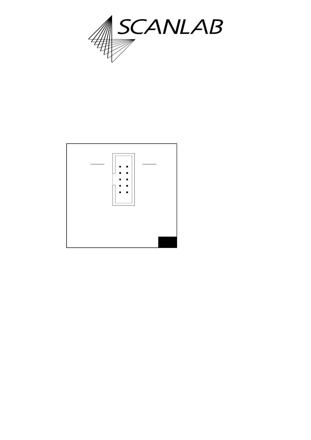
30
STEPPER MOTOR socket connector: pin-out. The pitch of
the pins is 2.54 mm.
(1) See footnote on page 73.
109
21
SWITCH1 (01) (02) SWITCH2
ENABLE1 (03) (04) ENABLE2
DIRECTION1 (05) (06) DIRECTION2
CLOCK1 (07) (08) CLOCK2
GND (09) (10) GND
Identical in construction to Würth 61201021621.