RTC6 boards
Doc. Rev. 1.0.21 en-US
7 Basic Functions for Scan Head Control and Laser Control
207
7.4.10 Synchronization of the RTC6
Clock Cycle and an External
Clock Signal
The laser pulse signals of a free-running laser and the
laser control of the RTC6 PCIe Board can be
synchronized. Non-flush line starts are thereby
avoided, see Figure 60.
Here, the RTC6 PCIe Board accepts the external clock
signal as the master clock. It must be supplied at the
digital input port DIGITAL IN1 of the
LASER Connector.
The synchronization is switched on and off by Bit #6
of set_laser_control. By Bit #5, it can be set whether
to use the rising or falling edge of the external clock
for synchronization. This automatically synchronizes
the RTC6-internal Laser Control Signals to the
external clock signals.
Notes
• The frequency of the master clock must meet the
following requirements:
f = k × 100 kHz (k 64) and
f = 64 MHz / n (k and n integer).
Therefore, only the following frequencies can be
used: 100 kHz, 200 kHz, 400 kHz, 500 kHz,
800 kHz, 1 MHz, 1.6 MHz, 2 MHz, 3.2 MHz,
4 MHz, 6.4 MHz. The allowed external frequency
deviation from an integer multiple of 100 kHz is
±15.625 ns per 10 µs.
• The supplied clock signal must be a TTL signal.
The minimum pulse length or pulse pause of the
clock signal should be 80 ns. See also
Chapter 4.6.1 ”LASER Connector”, page 73,
Section ”2-Bit Digital Input Port”, page 74.
• No synchronization is carried-out, if the
synchronization is activated but there is no
valid clock signal at DIGITAL IN1 of the LASER-
connector. In this case the RTC6 PCIe Board uses
its internal 10 µs clock cycle.
• If the synchronization is activated by
set_laser_control by setting Bit #6, then the
synchronization of RTC6 PCIe Board and external
clock is subtly (depending on the respective phase
position within 1.2 ms at most).
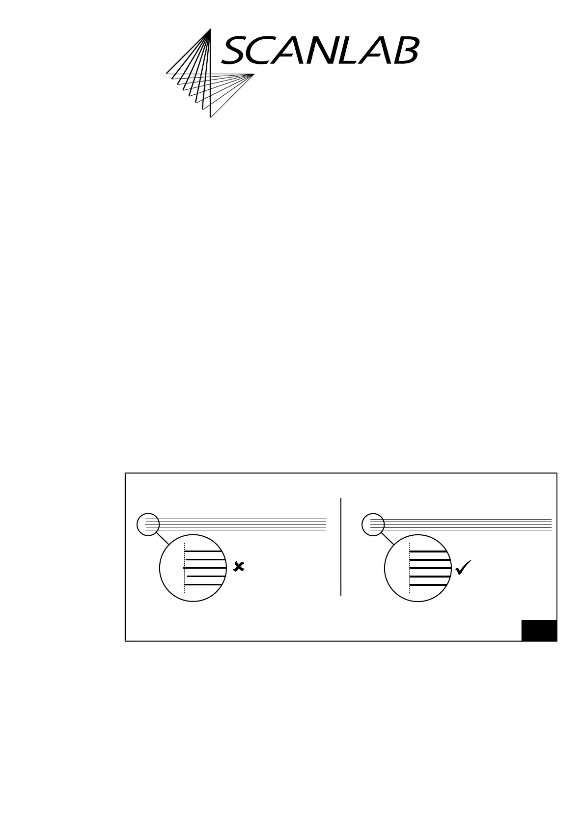
60
Free-running laser and RTC6 PCIe Board – example of marked lines.
flush
line starts
RTC6 10 µs clock period and laser pulses of the
free-running laser are synchronized:
non-flush
line starts
RTC6 10 µs clock period and laser pulses of the
free-running laser are not synchronized: