RTC6 boards
Doc. Rev. 1.0.21 en-US
4 RTC6 PCIe Board – Layout and Interfaces
68
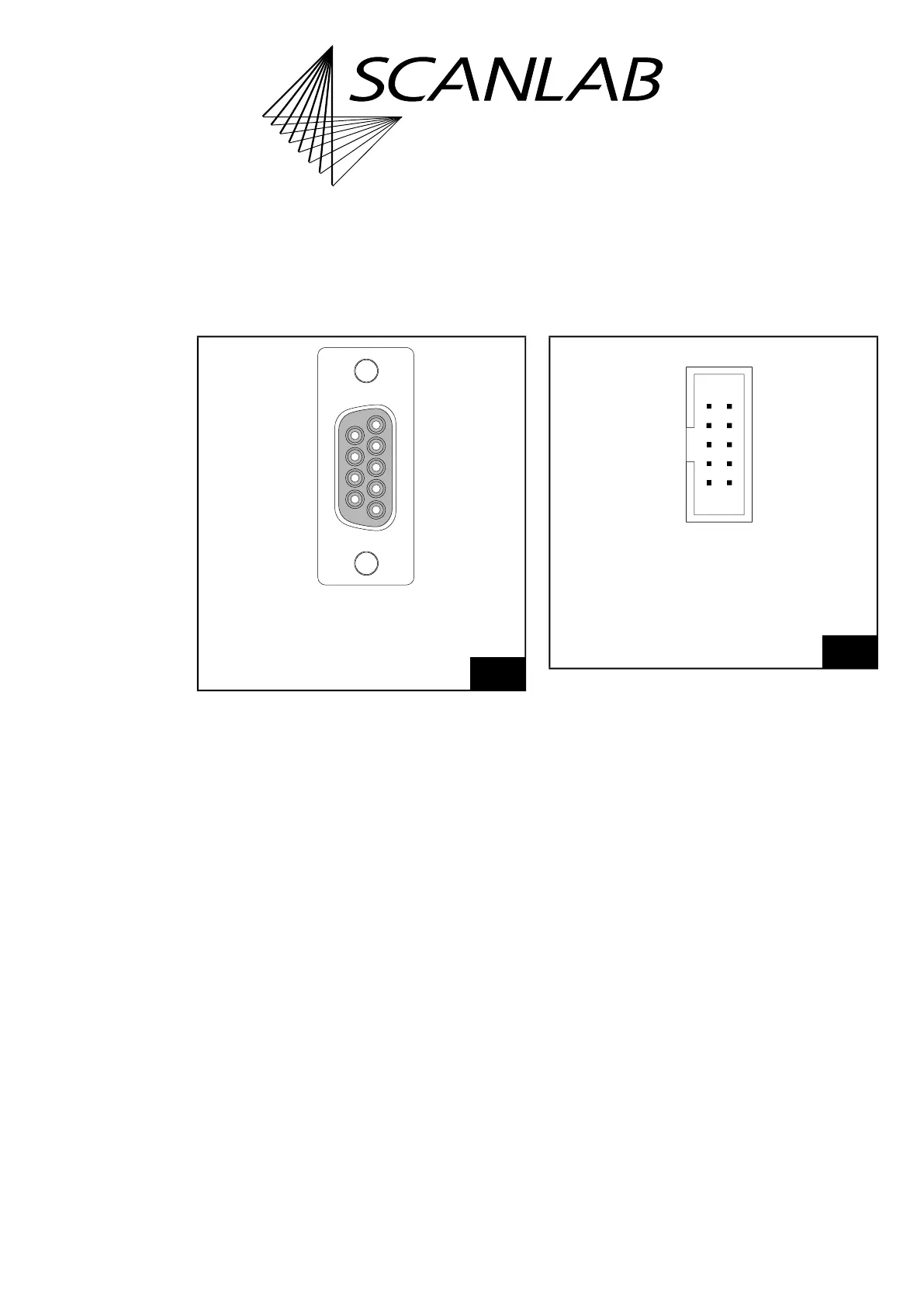
SCANHEAD Connector
(connector for the first scan head)
The pin-out of the first scan head connector
SCANHEAD (D-SUB 9-pin female) is shown in
Figure 10.
At the differential DATA OUT output port, the control
values for the scan system are outputted.
The differential DATA IN input port receives the
status signals returned by the scan system.
Pin (02) supplies 3.3 V power for the
XY2-100 Converter (Accessory) (or a
Polymer Optical Fiber converter for optical data
transmission). This voltage should not be used for
other purposes.
2. SCANHEAD Socket Connector
(connector for the second scan head)
The pin-out of the second scan head connector
2. SCANHEAD (10-pin socket connector) is shown in
Figure 11.
Second Scan Head Slot Cover (Accessory)
SCANLAB recommends using an additional slot cover
for connecting a second scan head or a z axis to the
2. SCANHEAD Socket Connector, see Chapter 2.8.4
”Slot Cover with 9-pin D-SUB Connector for
“2. SCANHEAD” Socket Connector”, page 45.
10
SCANHEAD connector (9-pin female D-SUB connector):
pin-out.
9
5
6
1
(05) DATA OUT+
(04) NOT CONNECTED
(03) NOT CONNECTED
(02) +3.3 V *
(01) DATA IN+
DATA OUT– (09)
GND (08)
GND (07)
DATA IN– (06)
* DO NOT CONNECT
11
2. SCANHEAD socket connector: pin-out. The pitch of the
pins is 2.54 mm. Signals for second scan head are only
outputted with enabled Option “Second Scan Head
Control”.
DATA IN+ (01) (02) DATA IN–
+3.3 V * (03) (04) GND
NOT CONNECTED (05) (06) GND
NOT CONNECTED (07) (08) DATA OUT–
DATA OUT+ (09) (10) NOT CONNECTED
* DO NOT CONNECT
Identical in construction to Würth 61201021621.