RTC6 boards
Doc. Rev. 1.0.21 en-US
7 Basic Functions for Scan Head Control and Laser Control
167
7.3 Scan Head Control
7.3.1 Reference System
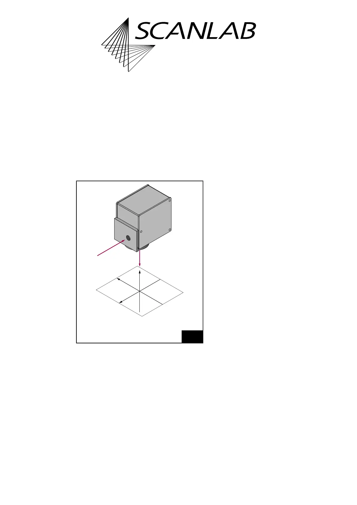
The reference system for the Image Field which is
used by the RTC6 PCIe Board is shown in Figure 47.
The y axis points in the reverse direction of the input
laser beam, the z axis points in the reverse direction
of the output laser beam. x axis, y axis and z axis form
a right-handed reference system. The origin of the
reference system, that is, the point (0|0|0), is in the
center of the Image Field.
7.3.2 Image Field Size and Image
Field Calibration
The size of the usable Image Field is determined by
the maximum scan angle and the focal length of the
objective or the working distance (that is, the
distance between the input laser beam axis and the
Image Field).
The x, y and z coordinates of a vector must be
specified as signed 20-bit values (that is, as numbers
between –524,288 and +524,287).
The calibration factor K defines the ratio of the digital
point coordinates in bits
(1)
and the actual position of
the point in millimeters.
Let a
0
denote the side length of the Image Field given
by the maximum scan angle. The theoretical
calibration factor is then K
0
= 2
20
/a
0
[bits per
mm
(1)
].
SCANLAB provides a rounded value for the
calibration factor K. This value is slightly larger than,
but close to, the theoretical value. The actual
calibration factor K can be read out from a used
correction table by get_table_para or
get_head_para.
Given the calibration factor K, the side length a of the
usable Image Field in millimeters can be calculated:
47
Reference system for the RTC6 coordinates.
(0|0|0)
Z
Y
X
laser beam
out
laser beam
in
(1) The expression “bits” is here synonymous with “digital
control value” (see footnote
(3)
on page 136).
a
2
20
K
-------=