RTC6 boards
Doc. Rev. 1.0.21 en-US
7 Basic Functions for Scan Head Control and Laser Control
168
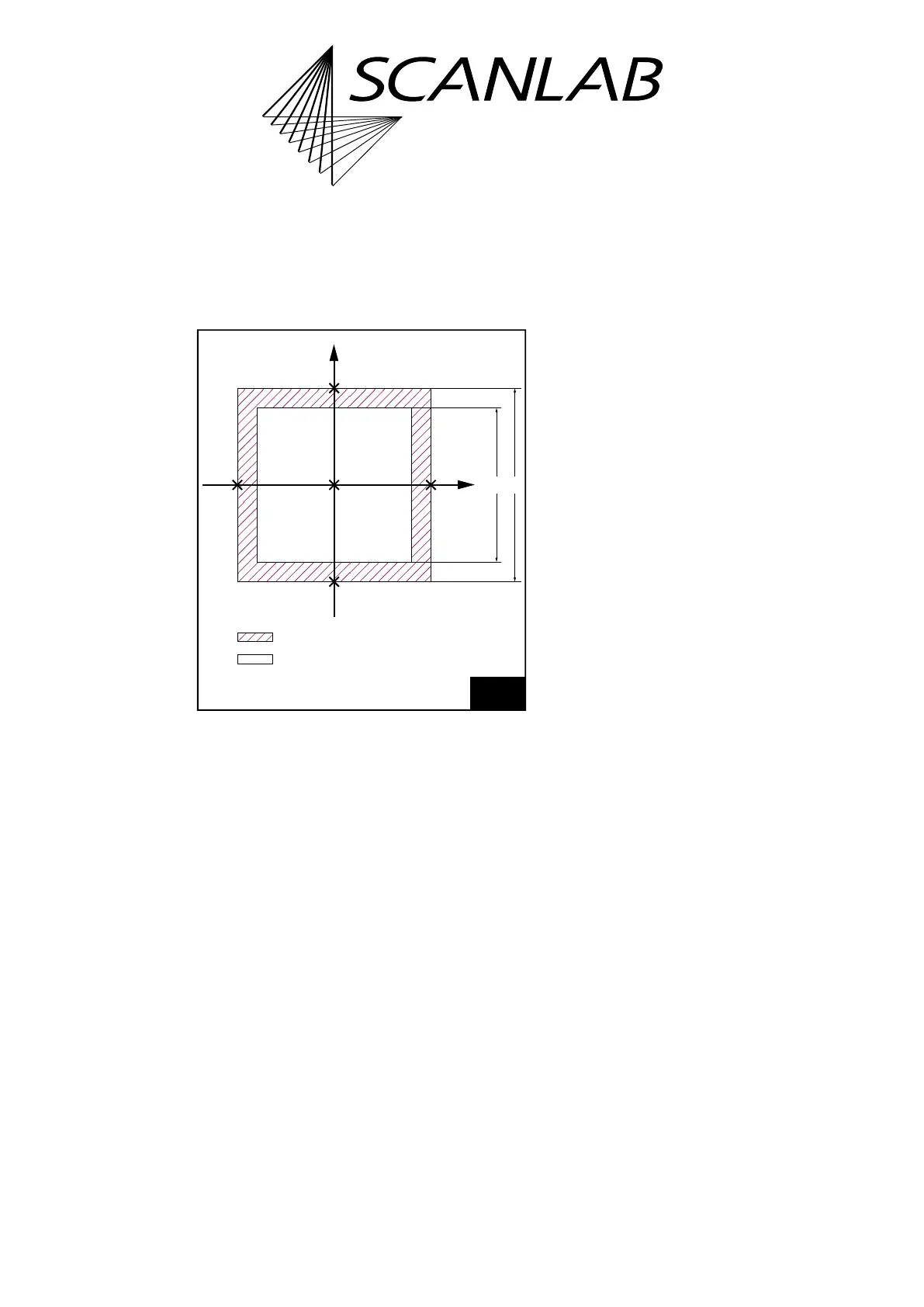
Typical Image Field
In general, the size of the usable (or “typical”) Image
Field – dependent on the objective and the optical
configuration of the scan system – is smaller than the
maximum adjustable Image Field.
The scan head has a usable Image Field. If the laser
focus moves outside this field, some vignetting of the
laser beam can occur. The interior of the scan head
can be damaged due to excessive absorption of laser
power. Refer to your scan head operating manual’s
section on objectives.
• Compare the calculated side length a of the
maximum adjustable Image Field with the side
length b of the usable Image Field given in the
technical specifications of your scan head manual
(see Figure 48).
• If the laser focus is to be restricted to points
within the usable Image Field, the absolute values
of the x and y coordinates (in bits) must be
smaller than the maximum value M, where M
is the calibration factor K multiplied by half the
side length of the usable Image Field:
M = K × b/2
Compatibility Modes
RTC6 Standard Mode
(Default after load_program_file and
set_rtc6_mode)
The Image Field coordinates for the x axis, y axis and
z axis and all related parameters (for example,
jump speed or wobbel amplitude) are to be specified
as signed 20-bit values.
RTC5 Compatibility Mode
(set_rtc5_mode)
The Image Field coordinates for the x axis and y axis
and all associated parameters are to be specified as
signed 20-bit values – as in RTC6 Standard Mode.
See also Chapter 2.12.2 ”Adapting RTC5 Source Code
for the RTC6 PCIe Board”, page 60.
The Image Field coordinates of the z axis are to be
specified as signed 16-bit values. The
RTC6 PCIe Board automatically multiplies all
z coordinates by 16
(1)
.
As the z calibration factor, a value 16 times smaller
must be used.
RTC4 Compatibility Mode
(set_rtc4_mode)
The Image Field coordinates for the x axis, y axis and
z axis and all related parameters are to be specified as
signed 16-bit values. The RTC6 PCIe Board
automatically multiplies them by 16
(1)
.
As the xy calibration factor and z calibration factor, a
value 16 times smaller must be used. See also
Chapter 2.10.2 ”Porting RTC4 Source Code to the
RTC6 PCIe Board”, page 49.
48
Image field size.
ab
(0
|
0)
Y
X
Theoretically controllable image field.
Usable ("typical") image field.
(0 | –524,288)
(+524,287 | 0)
(0 | +524,287)
(–524,288 | 0)
(1) The allowed value range decreases accordingly.