RTC6 boards
Doc. Rev. 1.0.21 en-US
4 RTC6 PCIe Board – Layout and Interfaces
64
4 RTC6 PCIe Board – Layout and Interfaces
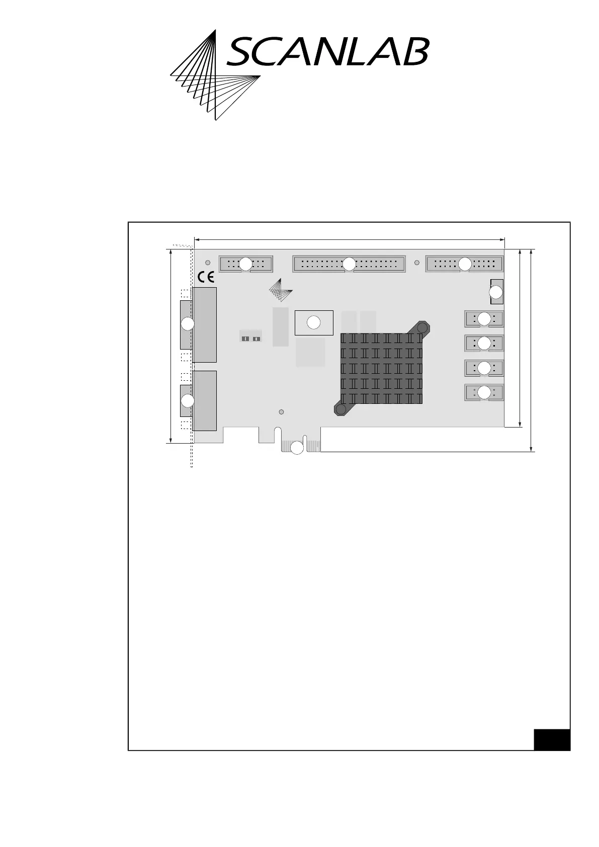
4.1 Layout – Upper Side
5
RTC6 PCIe Board: upper side.
109
21
109
21
109
21
109
21
2625
21
4039
21
1615
21
12
11
10
9
8
7
6
543
2
1
1
160 mm
LASER
SCANHEAD
SCANLAB
V1.2
RTC6
McBSP/ANALOG
RS232
STEPPER MOTOR
2. SCANHEAD
Slave
EXTENSION 2EXTENSION 1MARKING ON THE FLY
100 mm
104.5 mm
91.75 mm
Legend
1. SCANHEAD . . . . . . . . . . D-SUB connector 9-pin, female. Connector for the first scan head.
Pin-out see Figure 10.
2. LASER . . . . . . . . . . . . . . D-SUB connector 15-pin, female. Connector for the laser incl. digital and analog
output ports. Pin-out see Figure 17.
3. MARKING ON THE FLY . . 16-pin socket connector. With encoder input ports for Processing-on-the-fly applications.
Pin-out see Figure 25.
4. EXTENSION 1 . . . . . . . . . 40-pin socket connector. With a 16-bit digital input port and a 16-bit digital output port.
Pin-out see Figure 22.
5. EXTENSION 2 . . . . . . . . . 26-pin socket connector. With an 8-bit digital output port, for example, for alternative laser
control. Pin-out see Figure 24.
6. Slave . . . . . . . . . . . . . . . 6-pin socket connector. To connect with another RTC6 PCIe Board for clock synchronization.
For details, see Chapter 4.4 ”Master Socket Connector, Slave Socket Connector”, page 66.
7. 2. SCANHEAD . . . . . . . . 10-pin socket connector. Connector for a second scan head.
Pin-out see Figure 11.
8. STEPPER MOTOR . . . . . . 10-pin socket connector. For control of two stepper motors.
Pin-out see Figure 30.
9. RS232 . . . . . . . . . . . . . . 10-pin socket connector. For controlling external devices by RS-232 interface.
Pin-out see Figure 27.
10. McBSP/ANALOG. . . . . . 10-pin socket connector. Serial extension interface.
Pin-out see Figure 28.
11. PCIe-x-1 Plug . . . . . . . . Interface to the PC. See Chapter 4.3 ”Interface to the PC”, page 66.
12. . . . . . . . . . . . . . . . . . . Label with serial number.