RTC6 boards
Doc. Rev. 1.0.21 en-US
4 RTC6 PCIe Board – Layout and Interfaces
82
4.6.4 MARKING ON THE FLY Socket
Connector
The MARKING ON THE FLY socket connector has 16
pins and is located on the upper side of the
RTC6 PCIe Board, see Figure 5. It provides, among
other things, pins for encoder inputs.
If the Option Processing-on-the-fly of the board is
enabled, laser material processing of moving
workpieces (for example, on a moving conveyor belt
or rotating disk) can be implemented, see
Chapter 8.6 ”Processing-on-the-fly”, page 242.
The pin-out is shown in Figure 25.
Encoder Input Ports
The RTC6 PCIe Board provides two encoder
input ports:
• ENCODER X
• ENCODER Y
Each of the encoder input ports is designed for a pair
(1, 2) of standardized RS-422 differential signals. See
also Section ”Input Ports for External Encoder
Signals”, page 299.
External Control Signals
The external control signals /START2 and /STOP2
(TTL active-LOW) are referenced to GND
(1)
. Both input
signals are connected internally to +3.3 V by pull-up
resistors. See also Chapter 9.3.1 ”Starting and
Stopping Lists by External Control Signals
and Master/Slave Synchronization”, page 289.
Analog Output Port
The signal outputted at the 12-bit analog output port
ANALOG OUT2 of the LASER Connector is also
outputted at pin (14), see also Section ”12-Bit Analog
Output Port 1 and 2”, page 74.
The signal is referenced to GND
(1)
.
BUSY List Execution Status
The BUSY OUT signal at pin (13) is identical to the
BUSY OUT signal at the LASER Connector, see Section
”BUSY List Execution Status”, page 74.
The signal is referenced to GND
(1)
.
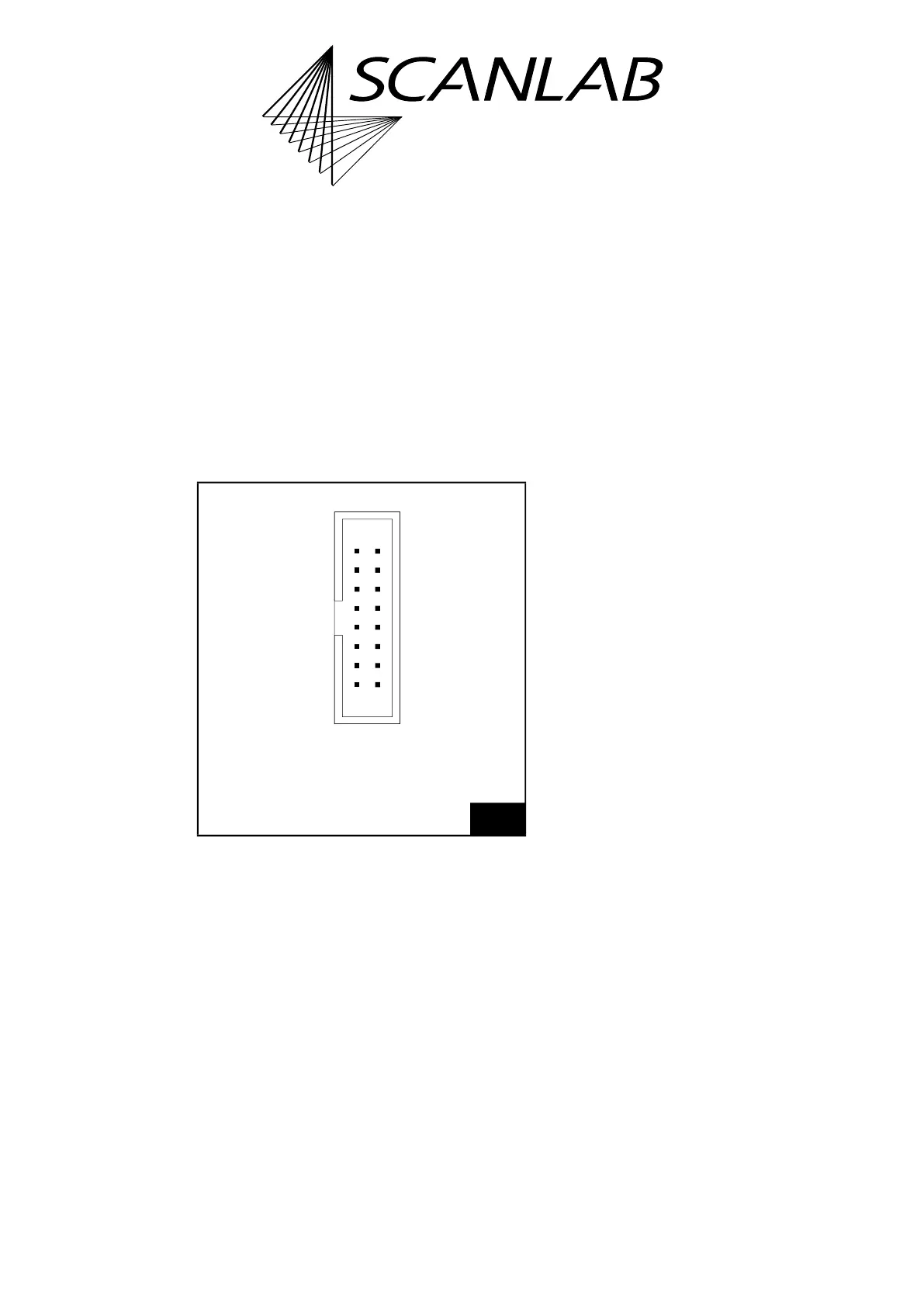
25
MARKING ON THE FLY socket connector: pin-out. The pitch
of the pins is 2.54 mm.
1615
21
+5 V (01) (02) GND
ENCODER X1– (03) (04) ENCODER X1+
ENCODER X2– (05) (06) ENCODER X2+
ENCODER Y1– (07) (08) ENCODER Y1+
ENCODER Y2– (09) (10) ENCODER Y2+
/STOP2 (11) (12) /START2
BUSY OUT (13) (14) ANALOG OUT2
GND (15) (16) NOT CONNECTED
Identical in construction to Würth 61201621621.
(1) See footnote on page 73.