RTC6 boards
Doc. Rev. 1.0.21 en-US
4 RTC6 PCIe Board – Layout and Interfaces
76
Laser Adapter (Accessory)
The SCANLAB laser adapter (accessory; #114774) is
plugged into the 15-pin LASER Connector of the
RTC6 PCIe Board. Then its 9-pin D-SUB connector
(female) provides the same signals and pin-out as the
RTC4 9-pin LASER connector.
Notes
• The laser adapter can not be directly plugged into
the RTC6 PCIe Board if an XY2-100 Converter
(Accessory) is already plugged in.
• The BUSY OUT signal, 2-bit digital input port and
2-bit digital output port are not available at the
laser adapter’s 9-pin D-SUB connector.
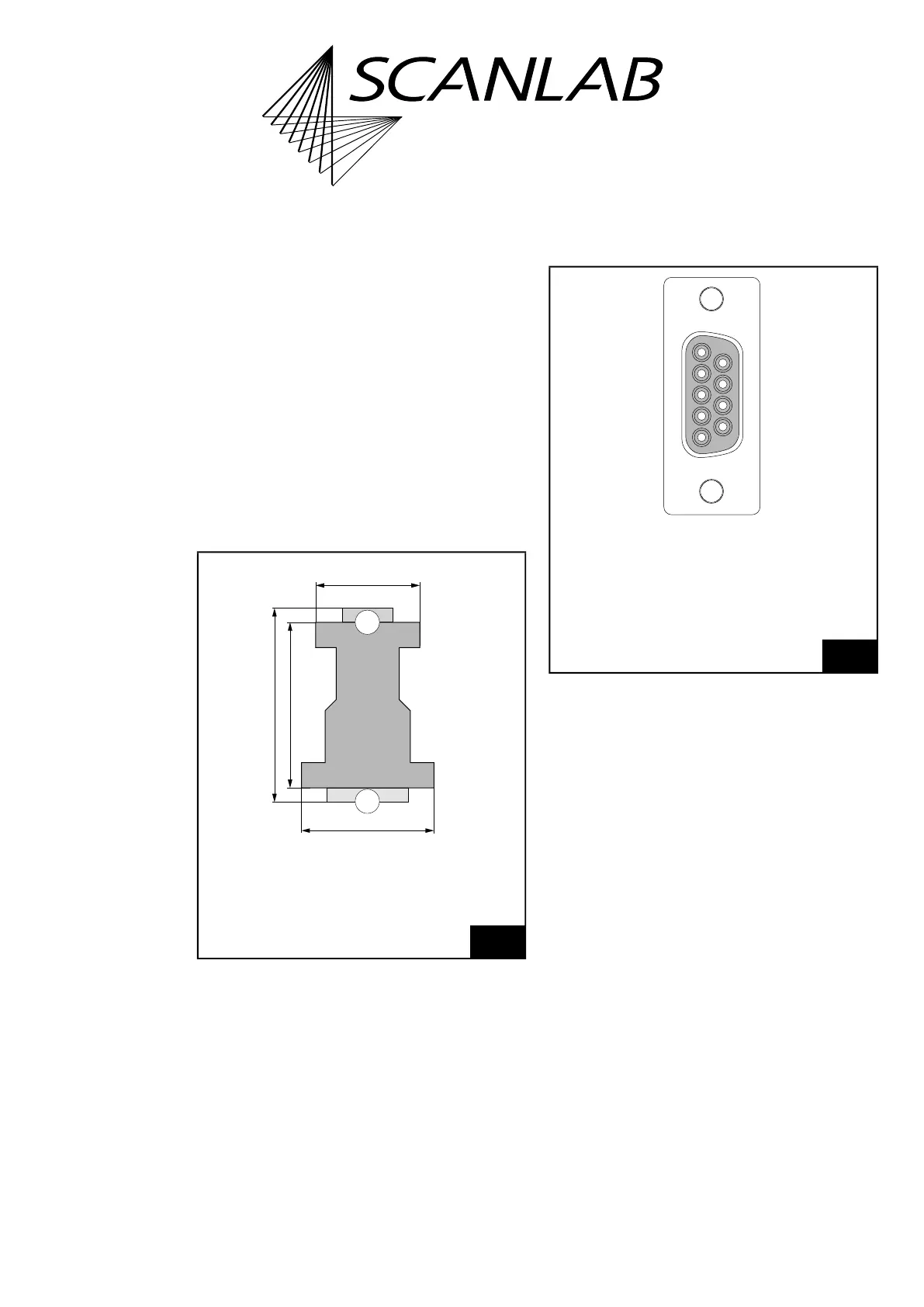
The dimensions of the laser adapter is shown in
Figure 19.
The pin-out of the 9-pin D-SUB connector is shown in
Figure 20.
The signals at pins (02) and (04) of the 9-pin D-SUB
connector can be selected by two solder jumpers in
the laser adapter. To do so, carefully open the laser
adapter housing by its 4 clip latches (for example,
using a screwdriver). The solder jumpers JP1 and JP2
are on the PCB of the laser adapter between the two
D-SUB connectors.
19
Laser adapter (accessory): dimensions.
2
1
42 mm
52 mm
62 mm
33 mm
Thickness
16 mm
Legend
1. 9-pin D-SUB connector, female
2. 15-pin D-SUB plug, male
20
Laser adapter (accessory): pin-out of the 9-pin D-SUB
connector, female.
LASER1 (01)
(06) GND2
* (02)
(07) GND2
LASER2 (03)
(08) /START
** (04)
(09) /STOP
GND (05)
** ANALOG OUT1 or +5 V,
dependent on the solder jumper setting
(on the PCB of the laser adapter)
* LASERON or ANALOG OUT2,
dependent on the solder jumper setting
(on the PCB of the laser adapter)