RTC6 boards
Doc. Rev. 1.0.21 en-US
4 RTC6 PCIe Board – Layout and Interfaces
73
4.6 Interfaces for the Laser and
Peripheral Equipment
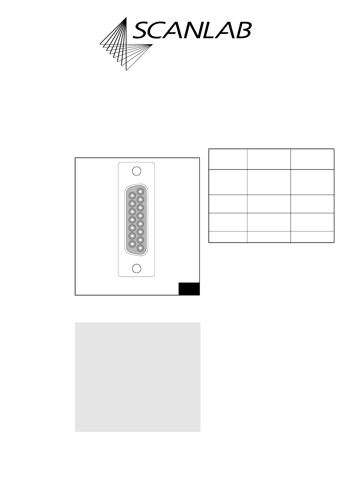
4.6.1 LASER Connector
The LASER Connector is a 15-pin D-SUB connector
(female). It is located on the slot cover of the
RTC6 PCIe Board, see Figure 5.
The pin-out is shown in Figure 17.
Laser Control Signals
Laser Control Signals are LASERON, LASER1 and
LASER2. They are digital TTL level signals and are
referenced to GND2.
Laser Control Signals LASER1 and LASER2 differ
depending on the set laser mode, see following table
and the timing diagrams in Chapter 7.4 ”Laser
Control”, page 184.
On RTC6 PCIe Boards with Option “DC/DC
Converter”, GND2 and the Laser Control Signals are
galvanically decoupled from GND
(1)
. On
RTC6 PCIe Boards without Option “DC/DC
Converter”, GND2 are GND identical, see Chapter 2.6
”Options”, page 38.
For the maximum current load see Chapter 15
”Technical Specifications – RTC6 PCIe Board”,
page 873.
Al Laser Control Signals can be set by
set_laser_control to either active-LOW or
active-HIGH logic. “active-LOW” means that a
logical 1 (“Laser On“, for instance) is represented by
a LOW level (0 V, TTL). “active-HIGH” means a
logical 1 is represented by a HIGH level (+5 V, TTL).
Set the TTL laser control signal level according to the
specifications of your laser control. Observe the
documentation of your laser.
Pin (01), (02) and (09) of the LASER Connector can be
configured by config_laser_signals and
config_laser_signals_list, see also Chapter 7.4.2
”Configuring the LASER Connector”, page 187.
17
LASER Connector (15-pin D-SUB connector, female):
pin-out. On RTC6 PCIe Boards without Option “DC/DC
Converter”, GND2 are GND identical.
Notice!
• If you want to use the RTC6 PCIe Board in
conjunction with laserDESK, observe the
following:
– laserDESK uses additional pins on the
EXTENSION 1 Socket Connector, for example,
to control the laser.
– Refer to the extended documentation for
connecting the laser. Refer to laserDESK
online help
(alternatively available from SCANLAB or in
laserDESK-zip, which can be downloaded
from the SCANLAB website).
15
8
9
1
ANALOG OUT2 (15)
(08) ANALOG OUT1
GND (14)
(07) +5 V
DIGITAL IN1 (13)
(06) DIGITAL IN2
DIGITAL OUT1 (12)
(05) DIGITAL OUT2
/STOP (11)
(04) BUSY OUT
GND2 (10)
(03) /START
LASER2 (09)
(02) LASERON
(01) LASER1
LASER1
pin (01)
LASER2
pin (09)
CO
2
Mode Modulation
pulse 1,
standby signal
Modulation
pulse 2,
standby signal
YAG Modes 1,
2, 3, 5
Q-Switch signal FirstPulseKiller
signal
Laser Mode 4 Standby signal FirstPulseKiller
signal
Laser Mode 6 Standby signal –
(1) With RTC6 PCIe Boards GND is the PC ground.
With RTC6 Ethernet Boards GND is the ground at the
POWER connector.