RTC6 boards
Doc. Rev. 1.0.21 en-US
4 RTC6 PCIe Board – Layout and Interfaces
72
15
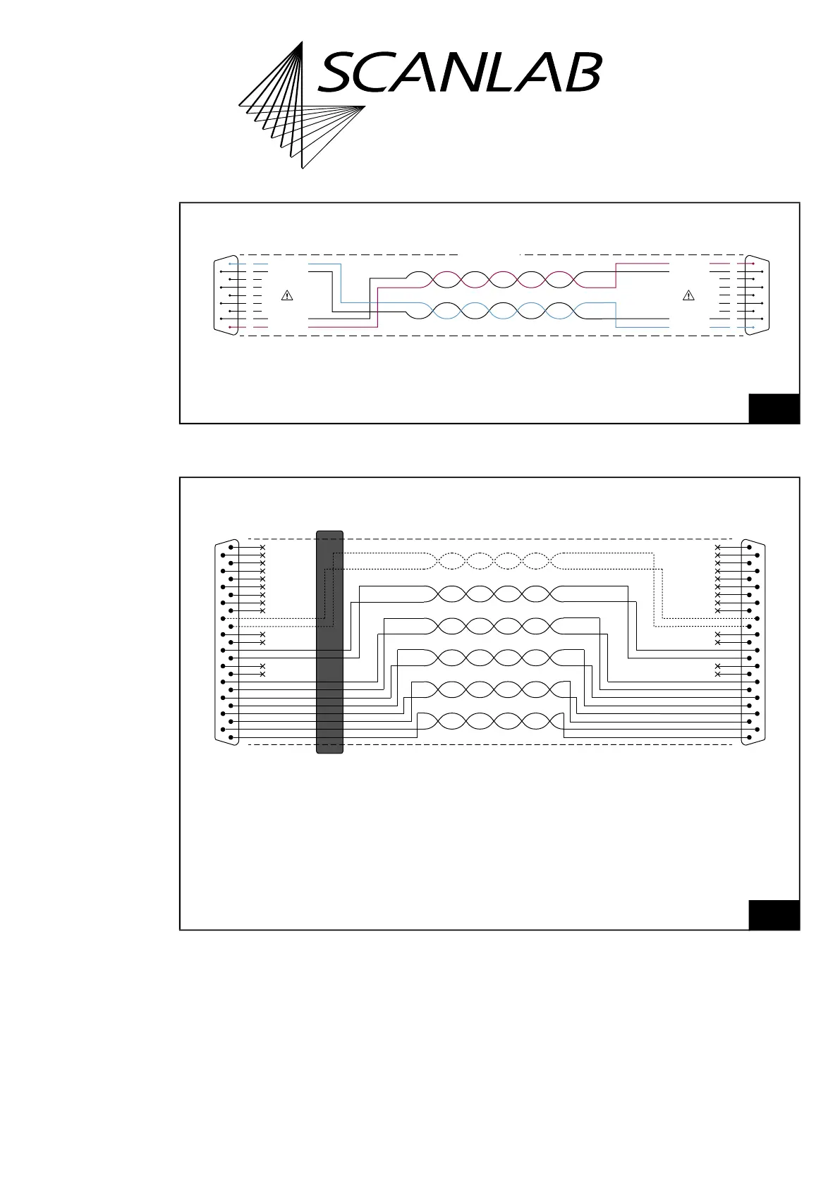
Cable for data transmission compliant to SL2-100 protocol: requirements and pin assignments:
requirements and pin assignments.
DATA
IN
+
DATA
IN
–
DATA OUT
–
DATA OUT
+
×
×
×
×
×
1
6
2
7
3
8
4
9
5
DATA
IN
+
DATA
IN
–
DATA OUT
–
DATA OUT
+
×
×
×
×
×
1
6
2
7
3
8
4
9
5
Scan system →
9-pin D-SUB connector, male
Shielding
← RTC board
9-pin D-SUB connector, male
Cable for SL2-100 protocol-compliant data transmission
16
Cable for data transmission compliant to XY2-100 protocol:
requirements and pin assignments.
CLOCK−
1
SYNC− 2
CHAN1− 3
CHAN2− 4
5
STATUS− * 6
7
STATUS1− * 8
9
10
11
12
13
CLOCK+ 14
SYNC+ 15
CHAN1+ 16
CHAN2+
17
18
STATUS+ *
19
20
STATUS1+ * 21
22
23
24
25
Ferrit
CLOCK−
1
SYNC−
2
CHAN1−
3
CHAN2−
4
5
STATUS− *6
7
STATUS1− *8
9
10
11
12
13
CLOCK+14
SYNC+15
CHAN1+16
CHAN2+17
18
STATUS+ *
19
20
STATUS1+ *21
22
23
24
25
Shielding
To RTC board
25-pin D-SUB connector, male
To scan head
25-pin D-SUB connector, male
Cable for XY2-100 protocol-compliant data transmission
* For iDRIVE scan systems (see Glossary entry on page 27), the following applies:
The STATUS± channel is the status channel for axis 2 (x axis;
this channel is also called STATUS2± there).
The STATUS1± channel is the status channel for axis 1 (y axis).
For other scan systems, the STATUS1± channel is not needed.