RTC6 boards
Doc. Rev. 1.0.21 en-US
4 RTC6 PCIe Board – Layout and Interfaces
78
4.6.2 EXTENSION 1 Socket Connector
The EXTENSION 1 socket connector has 40 pins. It is
located on the upper side of the RTC6 PCIe Board, see
Figure 5.
The pin-out is shown in Figure 22.
Configuring the Output Signal Level
With the solder jumper field A on the lower side of
the RTC6 PCIe Board, see Figure 6, the level of all
output signals at the EXTENSION 1 socket connector
(DIGITAL OUT 0…DIGITAL OUT 15, LATCH_OUT,
SYNC_OUT, BUSY OUT, VCC_OUT) can be configured
for 5 V or 3.3 V, see Chapter 2.7.1
”Solder Jumper Field A – Configuring Output Signal
Level at EXTENSION 1 Socket Connector”, page 41.
For monitoring purposes, the selected signal level is
continuously outputted at pin (35): signal VCC_OUT.
VCC_OUT is referenced to GND
(1)
.
The maximum current load of the signal is 100 mA.
16-Bit Digital Input Port and 16-Bit Digital
Output Port
The 40-pin EXTENSION 1 socket connector provides a
16-bit digital TTL input and a buffered 16-bit digital
TTL output, see Figure 22. This requires the output
signals level to be configured by the jumper setting,
see Section ”Configuring the Output Signal Level”,
page 78.
For programming, see
• Chapter 9.1.1 ”16-Bit Digital Output Port”,
page 282
• Chapter 9.2.1 ”16-Bit Digital Input Port”,
page 288
• Chapter 9.3.2 ”Conditional Command
Execution”, page 295
The input and output signals are referenced to
GND
(1)
.
The maximum current load of the output signals is
8 mA.
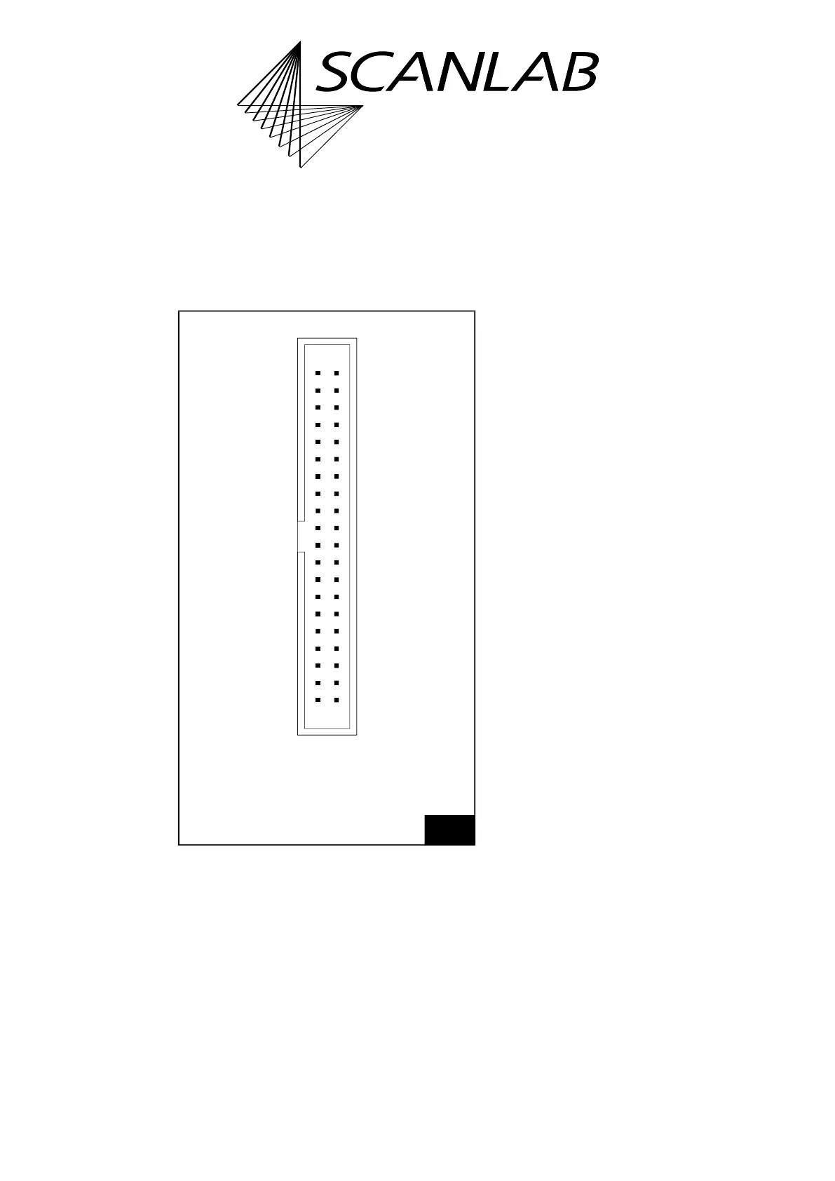
22
EXTENSION 1 socket connector: pin-out. The pitch of the
pins is 2.54 mm.
DIGITAL OUT 0 (01) (02) DIGITAL IN 0
DIGITAL OUT 1 (03) (04) DIGITAL IN 1
DIGITAL OUT 2 (05) (06) DIGITAL IN 2
DIGITAL OUT 3 (07) (08) DIGITAL IN 3
DIGITAL OUT 4 (09) (10) DIGITAL IN 4
DIGITAL OUT 5 (11) (12) DIGITAL IN 5
DIGITAL OUT 6 (13) (14) DIGITAL IN 6
DIGITAL OUT 7 (15) (16) DIGITAL IN 7
DIGITAL OUT 8 (17) (18) DIGITAL IN 8
DIGITAL OUT 9 (19) (20) DIGITAL IN 9
DIGITAL OUT 10 (21) (22) DIGITAL IN 10
DIGITAL OUT 11 (23) (24) DIGITAL IN 11
DIGITAL OUT 12 (25) (26) DIGITAL IN 12
DIGITAL OUT 13 (27) (28) DIGITAL IN 13
DIGITAL OUT 14 (29) (30) DIGITAL IN 14
DIGITAL OUT 15 (31) (32) DIGITAL IN 15
LATCH OUT (33) (34) SYNC OUT
VCC OUT (35) (36) BUSY OUT
+5 V (37) (38) +5 V
GND (39) (40) GND
Identical in construction to Würth 61204021621.
(1) See footnote on page 73.