RTC6 boards
Doc. Rev. 1.0.21 en-US
2 Product Overview
46
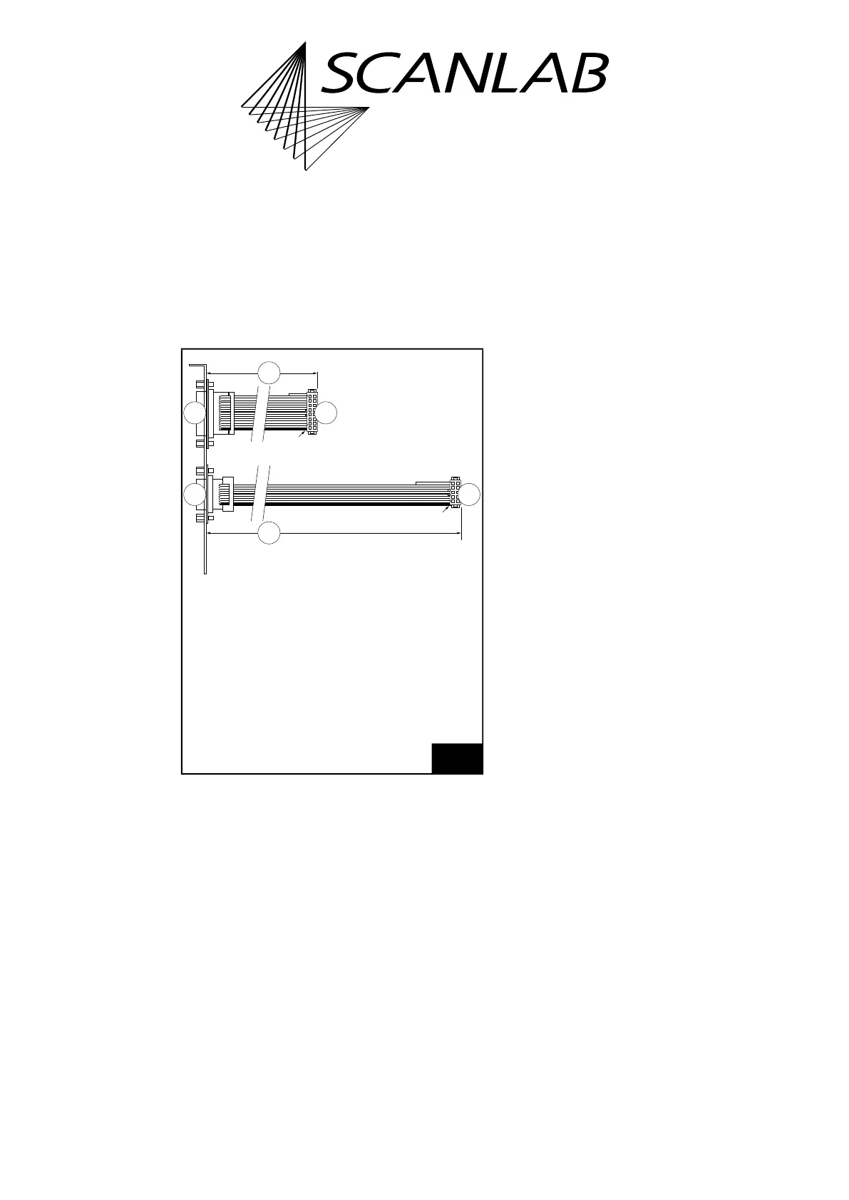
2.8.6 Slot Cover with 15-pin D-SUB
Connector and 9-pin D-SUB
Connector
The connectors of #115132 and 109272 together on
a single bracket (for the same purpose as these)
features bracket, see Figure 4:
• #130209
2.8.7 Extension Board
“RTC5/6 varioSCAN FLEX
Extension”
For RTC5/6 Boards, the “RTC5/6 varioSCAN 40 FLEX
Extension” extension board (#128683) is available
(1)
.
It has been specially developed to control analog and
digital varioSCAN 40 FLEX devices by SCANLAB
laserDESK software. A position change of the
varioSCAN 40 FLEX focusing optics is caused by the
step motor which changes the working distance of
the 3D scan system in the end.
For further information, refer to the pertaining
manual “Installation and Operation RTC5/6
varioSCAN FLEX Extension for RTC5 and RTC6
Control Boards”.
Notes
• “RTC5/6 varioSCAN 40 FLEX Extension” extension
board (#128683) does not support move_to
(2)
.
4
Slot cover #130209.
Legend
1. 15-pin D-SUB connector (female).
pin-out as Figure 26.
2. l = 105 mm.
3. To MARKING ON THE FLY Socket Connector.
4. 9-pin D-SUB connector (female).
pin-out as Figure 10.
5. l = 225 mm.
6. To 2. SCANHEAD Socket Connector.
(1) In contrast to “RTC4 STEP MOTOR EXTENSION”
extension board (#112097) – which can also be used
with RTC5 Boards – it has the advantage that the
EXTENSION 1 socket connector remains unoccupied.
(2) move_to has been introduced for
“RTC4 STEP MOTOR EXTENSION” extension board
(#112097).