RTC6 boards
Doc. Rev. 1.0.21 en-US
4 RTC6 PCIe Board – Layout and Interfaces
84
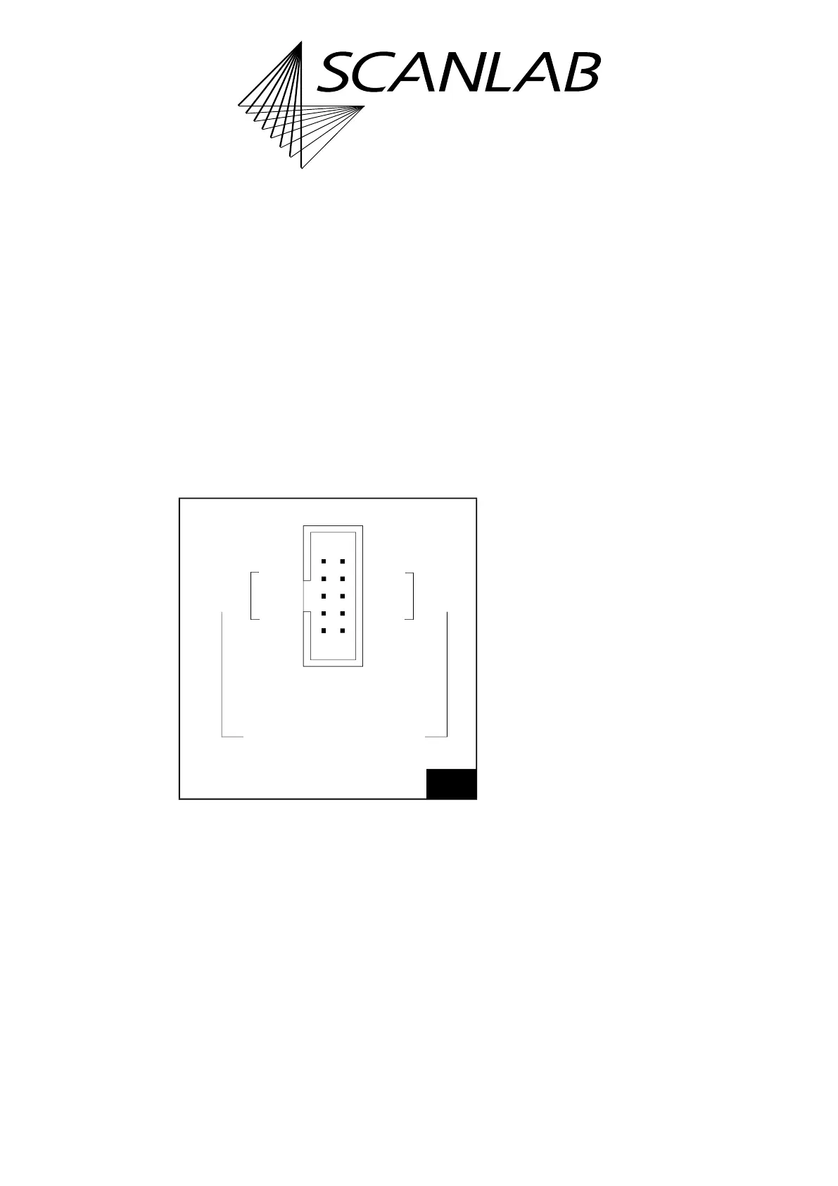
4.6.6 McBSP/ANALOG Socket
Connector
The McBSP/ANALOG socket connector
(1)
has 10 pins.
It is located on the upper side of the RTC6 PCIe Board,
see Figure 5.
The McBSP/ANALOG socket connector is a hardware
interface that
• is designed for bidirectional data exchange
(McBSP), see Section ”McBSP Interface”, page 84
and
• furthermore, provides two 10 V analog
input ports: ANALOG IN0 at pin (01) and
ANALOG IN1 at pin (02), see Section ”Analog
Input Ports”, page 86.
The pin-out is shown in Figure 28.
McBSP Interface
The McBSP interface, see Figure 28, is initialized by
load_program_file with:
•
XDelay
=
RDelay
= 1
• 8 MHz clock frequency
Intended for McBSP are pin (03), (05), (07) (outgoing
signals) and pin (04), (06), (08) (incoming signals).
The following signals are continuously outputted
after load_program_file:
• the clock signal at pin (03)
• every 10 µs a frame synchronization signal FSX
at pin (05)
• a data signal DX at pin (07) (Default:
SampleY|SampleX), see set_mcbsp_out
The McBSP interface can be integrated into
applications for various purposes:
• As an alternative to encoder signals, the position
of a moving workpiece can be directly integrated,
see also Chapter ”Correction via
McBSP Interface”, page 245. Prerequisite: Option
Processing-on-the-fly.
• As an alternative to matrix and offset commands,
coordinate transformations can be transmitted
and integrated to align a workpiece with
controllable timing (Online Positioning), see also
Chapter 9.3.4 ”Synchronization and
Online Positioning by McBSP Signals”, page 300.
• With set_multi_mcbsp_in you can transfer not
only a 3D fly correction with position information
but also laser power and other parameters, see
also Chapter ”Correction via McBSP Interface
with Additional McBSP Input”, page 246.
Prerequisite: Option Processing-on-the-fly.
• Permanent data output in 10 µs cycles. With
set_mcbsp_out and set_mcbsp_out_ptr it can
be selected which data signals are outputted.
• OIE Output Mode, page 696 can be set at the
McBSP interface by set_mcbsp_out_oie_ctrl and
set_mcbsp_out_oie_list.
(1) With RTC5 boards referred to as SPI /I2C
socket connector.
28
McBSP/ANALOG socket connector: pin-out. The pitch of the
pins is 2.54 mm.
Identical in construction to
ANALOG IN0 (01) (02) ANALOG IN1
CLKX0 (03) (04) CLKR0
FSX0 (05) (06) FSR0
DX0 (07) (08) DR0
GND (09) (10) 3,3 V
McBSP
McBSP
McBSP interface
Würth 61201021621.