RTC6 boards
Doc. Rev. 1.0.21 en-US
8 Advanced Functions for Scan Head Control and Laser Control
268
8.7.4 Synchronization
The pixel output timing diagram for one image line
with 3 pixels is shown in Figure 66.
To prepare the laser control,
set_pixel_line/set_pixel_line_3d switches off the
Signals for “Laser Active” Operation from a previous
Mark Command after a LaserOff Delay (as with a
Jump Command) and waits until the laser is actually
off.
During this waiting period, the
galvanometer scanners do not move in “Classic
Mode” (Mode = 0, see page 712) only. In all other
modes, they continue to move at the speed defined
by
HalfPeriod
and pixel distance in equidistant
Microsteps. This allows to program jerk-free run-in
and run-out movements. Initial acceleration phases
can be hidden by a LaserOn Delay (as with a normal
[*]mark[*] Command) or by a corresponding number
of “idle pixels” (see below).
After that, depending on the laser mode, pixel
output starts immediately or after a Q-Switch delay,
see Figure 66. Analog signals at ANALOG OUT1 or
ANALOG OUT2 change synchronously with the
leading edge of each pixel pulse. The digital-to-
analog converter requires about 1.5 µs…3 µs to
produce a stable analog output signal. With pixel
output frequencies above around 100 kHz
(
HalfPeriod
< approx. 320) digital-to-analog
conversion cannot always be fully completed. At such
pixel output frequencies, it must be carefully checked
whether the functionality is sufficient for the
intended purpose.
Bit #1 in
set_laser_control( Ctrl )
can be used to
shift the laser pulse and thus the start of the digital-
to-analog conversion by half a pixel period.
The pixel line ends with the first list command that is
not a set_pixel or set_n_pixel.
For the laser to be switched off even in the middle of
a 10 µs cycle, a default pixel is automatically
outputted after the last pixel. This is repeated as
often as necessary until a started 10 µs cycle is
finished. Then the laser is finally switched off.
The default pixel should be defined appropriately
prior to set_pixel_line/set_pixel_line_3d in order to
achieve a non-visible laser marking (= “idle pixels”) in
the run out, see set_port_default and
set_default_pixel.
The RTC6 board waits – especially at pixel output
frequencies < 100 kHz – until the default pixel is
outputted.
The galvanometer scanners continue to run during
this time, to ensure jerk-free connection movements
(programmed by the user). No scanner delay is
automatically inserted. In “Classic Mode” (Mode = 0,
see page 712), the galvanometer scanners remain
idle for a few clock cycles. With Mode + 256 this can
be suppressed (even for the forerun phase).
The Tracking Error and the hidden acceleration phase
mean a pixel line shift”, see Figure 66. Normally, this
needs to be compensated for by an adjusted run-in.
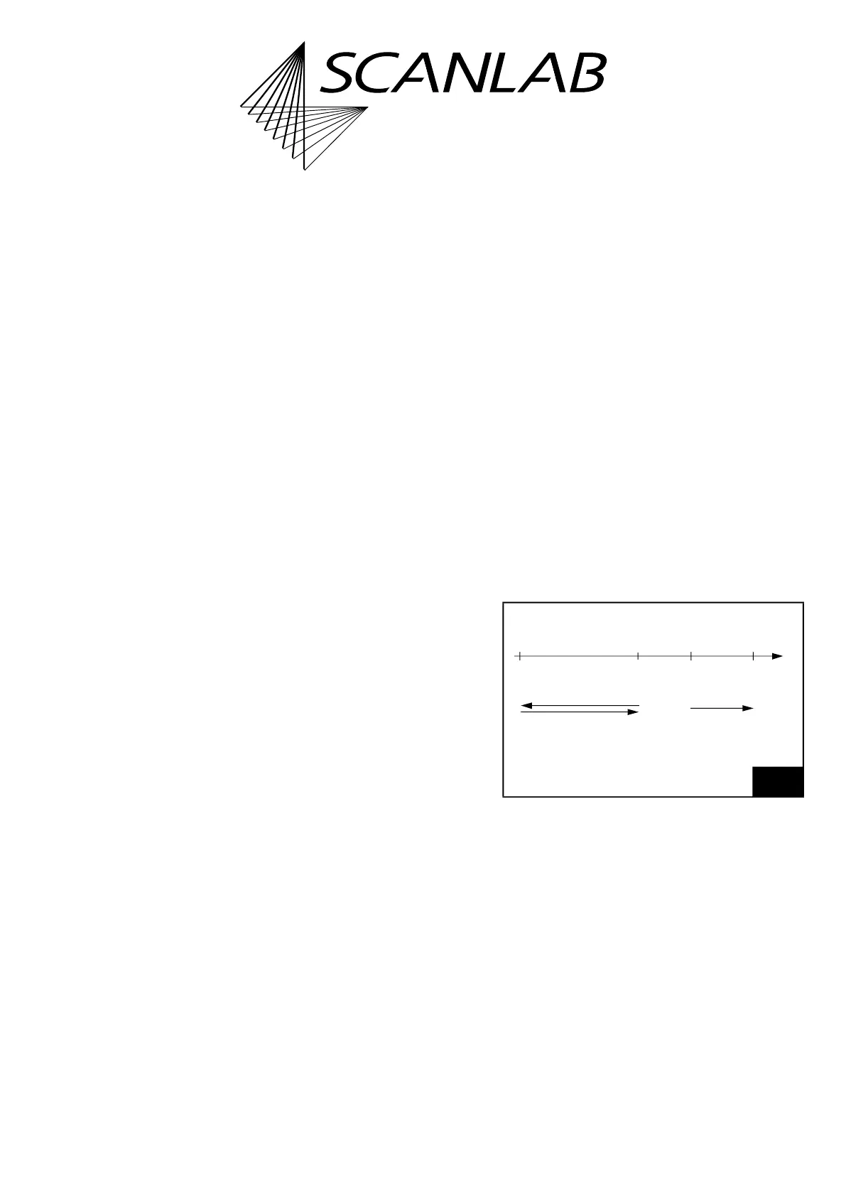
To make this easier, Mode + 512 can be used to
switch on Sky Writing Mode 1-similar movements in
the run-in and run-out phase and thus place the pixel
line with pinpoint accuracy, see Figure 65.
These movements cannot be combined with
Sky Writing Mode 2. The duration of the swing-out
movement must be explicitly defined via
Nprev
of
set_sky_writing_para in advance.
(1)
65
Modus + 512
(1) With excelliSCAN scan heads
, Sky Writing and
automatic delay calculation need to be switched on,
see “excelliSCAN Scan Heads – Functional Principle of
SCANahead Servo Control and Operation by RTC6
Boards” Manual.
Swing-out
movement
Post
movement
Phase Phase
Pixel
Run-in Run-outline
Nprev
Nprev
t