RTC6 boards
Doc. Rev. 1.0.21 en-US
8 Advanced Functions for Scan Head Control and Laser Control
269
Notes
• With
HalfPeriod
<
PulseLength
/ 2 the laser does
not switch off between the pixels.
• When specifying
HalfPeriod
and pixel distance,
observe the dynamics of the scan system
(mark speed) and the properties of the laser
system (power modulation).
66
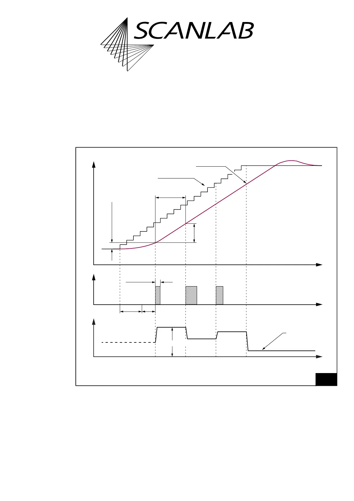
Timing of the galvanometer scanner positions and the Laser Control Signals in the Pixel Mode Mode = 0and a YAG Mode,
see Chapter 7.4.4 ”YAG Modes 1, 2, 3, 5”, page 190.
The pixel output period in this example is approx. 4.5 Microsteps.
dX,
dY
PulseLength = 0
PulseLength
Pixel 2Pixel 1Pixel 0
Galvanometer scanner positionPixel pulses
LaserOn
delay
Time
Actual position
Set position
(microsteps)
Q
-
Switch
delay
AnalogOut = 0xFFF
or acc.
set_laser_off_default
or
set_port_default
AnalogOut
pixel values
Pixel output period
= 2 ×
HalfPeriod
Analog signal
Time
Time
Pixel line shift
Default pixel