RTC6 boards
Doc. Rev. 1.0.21 en-US
8 Advanced Functions for Scan Head Control and Laser Control
266
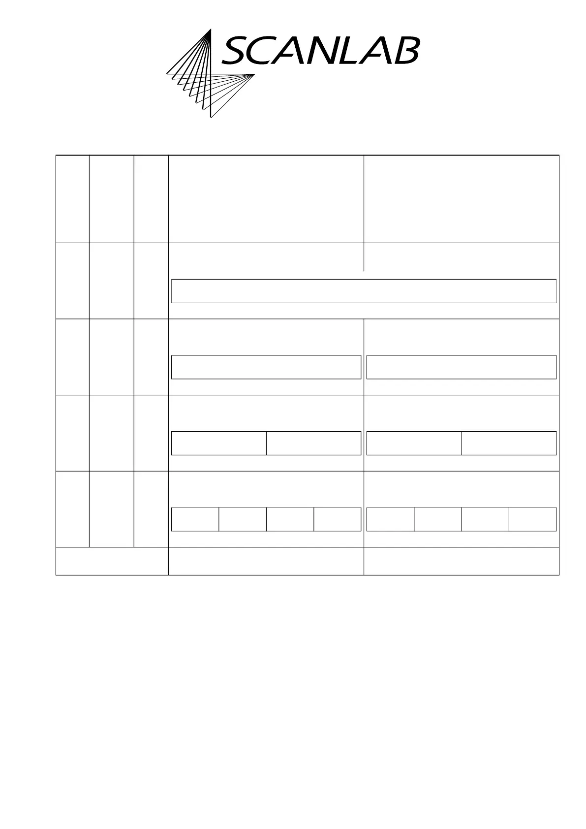
Table 5:
Mode Max. fre-
quency
No. of
pixels
per
set_pix
el/
set_n_
pixel
1
st
parameter of set_pixel/set_n_pixel
(name:
PortOutValue1
(a)
)
2
nd
parameter of set_pixel/set_n_pixel
(name:
PortOutValue2
(b)
)
0,
256
(c)
400 kHz 1 Pixel 1 (defined by the pulse length).
The output is done as signal LASER1.
Port output (but not port 5) for Pixel 1
16 800 kHz 2 Port output for Pixel 1
(up to 32 bits per pixel, depending on port)
Port output for Pixel 2
(up to 32 bits per pixel, depending on port)
32
(d)
1.6 MHz 4 Port output for Pixel 1, 2
(up to 16 bits per pixel, depending on port)
Port output for Pixel 3, 4
(up to 16 bits per pixel, depending on port)
64
(d)
3.2 MHz 8 Port output for Pixel 1, 2, 3, 4
(up to 8 bits per pixel, for all ports)
Port output for Pixel 5, 6, 7, 8
(up to 8 bits per pixel, for all ports)
Bit 31…………………………………………Bit 0 Bit 31…………………………………………Bit 0
(a)
PulseLength
in RTC6 Software Packages < v1.3.3.
(b)
AnalogOut
in RTC6 Software Packages < v1.3.3.
(c) The galvanometer scanner movement is not continuous in Mode = 0 and continuous in Mode = 256.
(d) > 800 kHz only possible with Option “UFPM“.
Pixel 1
(1
st
parameter: 32-bit; 2
nd
parameter: up to 16 bit, depending on port)
Pixel 1 Pixel 2
Pixel 2 Pixel 1 Pixel 4 Pixel 3
Pixel 4 Pixel 3 Pixel 2 Pixel 1 Pixel 8 Pixel 7 Pixel 6 Pixel 5