DocID024597 Rev 5 1365/1830
RM0351 Universal synchronous asynchronous receiver transmitter (USART)
1411
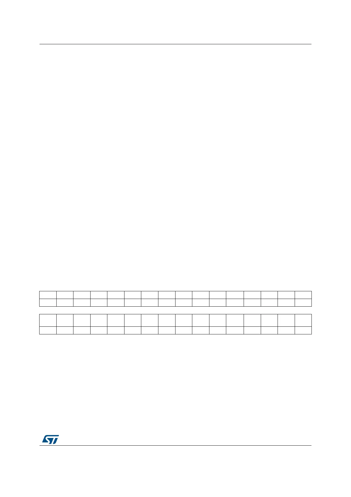
40.8.9 Interrupt flag clear register (USART_ICR)
Address offset: 0x20
Reset value: 0x0000
Bit 2 NF: START bit Noise detection flag
This bit is set by hardware when noise is detected on a received frame. It is cleared by
software, writing 1 to the NFCF bit in the USART_ICR register.
0: No noise is detected
1: Noise is detected
Note: This bit does not generate an interrupt as it appears at the same time as the RXNE bit
which itself generates an interrupt. An interrupt is generated when the NF flag is set
during multibuffer communication if the EIE bit is set.
Note: When the line is noise-free, the NF flag can be disabled by programming the ONEBIT
bit to 1 to increase the USART tolerance to deviations (Refer to Section 40.5.5:
Tolerance of the USART receiver to clock deviation on page 1320).
Bit 1 FE: Framing error
This bit is set by hardware when a de-synchronization, excessive noise or a break character
is detected. It is cleared by software, writing 1 to the FECF bit in the USART_ICR register.
In Smartcard mode, in transmission, this bit is set when the maximum number of transmit
attempts is reached without success (the card NACKs the data frame).
An interrupt is generated if EIE = 1 in the USART_CR1 register.
0: No Framing error is detected
1: Framing error or break character is detected
Bit 0 PE: Parity error
This bit is set by hardware when a parity error occurs in receiver mode. It is cleared by
software, writing 1 to the PECF in the USART_ICR register.
An interrupt is generated if PEIE = 1 in the USART_CR1 register.
0: No parity error
1: Parity error
31 30 29 28 27 26 25 24 23 22 21 20 19 18 17 16
Res. Res. Res. Res. Res. Res. Res. Res. Res. Res. Res. WUCF Res. Res. CMCF Res.
rc_w1 rc_w1
1514131211109876543210
Res. Res. Res. EOBCF RTOCF Res. CTSCF LBDCF
TCBGT
CF
TCCF Res. IDLECF ORECF NCF FECF PECF
rc_w1 rc_w1 rc_w1 rc_w1 rc_w1 rc_w1 rc_w1 rc_w1 rc_w1 rc_w1 rc_w1
Bits 31:21 Reserved, must be kept at reset value.
Bit 20 WUCF: Wakeup from Stop mode clear flag
Writing 1 to this bit clears the WUF flag in the USART_ISR register.
Note: If the USART does not support the wakeup from Stop feature, this bit is reserved and
forced by hardware to ‘0’.
Bits 19:18 Reserved, must be kept at reset value.
Bit 17 CMCF: Character match clear flag
Writing 1 to this bit clears the CMF flag in the USART_ISR register.
Bits 16:13 Reserved, must be kept at reset value.
 Loading...


