DocID024597 Rev 5 1367/1830
RM0351 Universal synchronous asynchronous receiver transmitter (USART)
1411
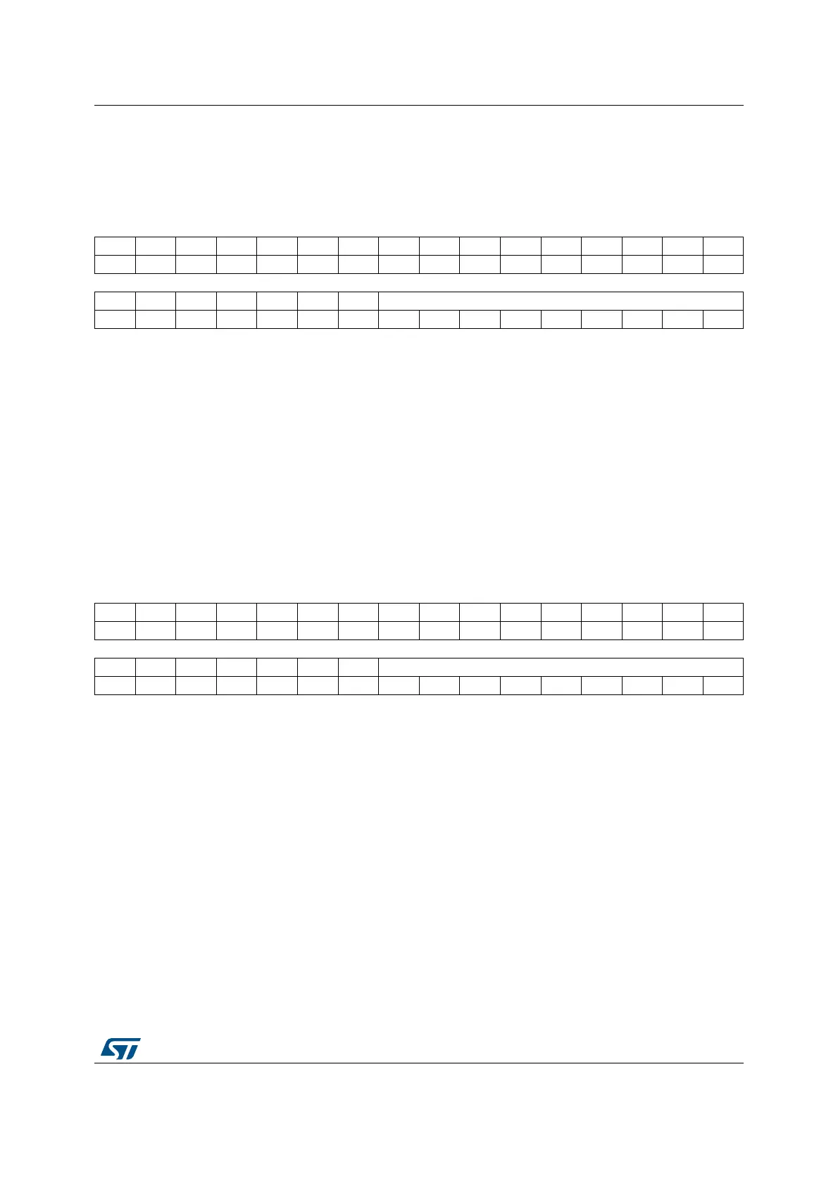
40.8.10 Receive data register (USART_RDR)
Address offset: 0x24
Reset value: Undefined
40.8.11 Transmit data register (USART_TDR)
Address offset: 0x28
Reset value: Undefined
31 30 29 28 27 26 25 24 23 22 21 20 19 18 17 16
Res. Res. Res. Res. Res. Res. Res. Res. Res. Res. Res. Res. Res. Res. Res. Res.
1514131211109876543210
Res. Res. Res. Res. Res. Res. Res. RDR[8:0]
rrrrrrrrr
Bits 31:9 Reserved, must be kept at reset value.
Bits 8:0 RDR[8:0]: Receive data value
Contains the received data character.
The RDR register provides the parallel interface between the input shift register and the
internal bus (see Figure 406).
When receiving with the parity enabled, the value read in the MSB bit is the received parity
bit.
31 30 29 28 27 26 25 24 23 22 21 20 19 18 17 16
Res. Res. Res. Res. Res. Res. Res. Res. Res. Res. Res. Res. Res. Res. Res. Res.
1514131211109876543210
Res. Res. Res. Res. Res. Res. Res. TDR[8:0]
rw rw rw rw rw rw rw rw rw
Bits 31:9 Reserved, must be kept at reset value.
Bits 8:0 TDR[8:0]: Transmit data value
Contains the data character to be transmitted.
The TDR register provides the parallel interface between the internal bus and the output
shift register (see Figure 406).
When transmitting with the parity enabled (PCE bit set to 1 in the USART_CR1 register),
the value written in the MSB (bit 7 or bit 8 depending on the data length) has no effect
because it is replaced by the parity.
Note: This register must be written only when TXE=1.
 Loading...


