DocID024597 Rev 5 643/1830
RM0351 Digital-to-analog converter (DAC)
647
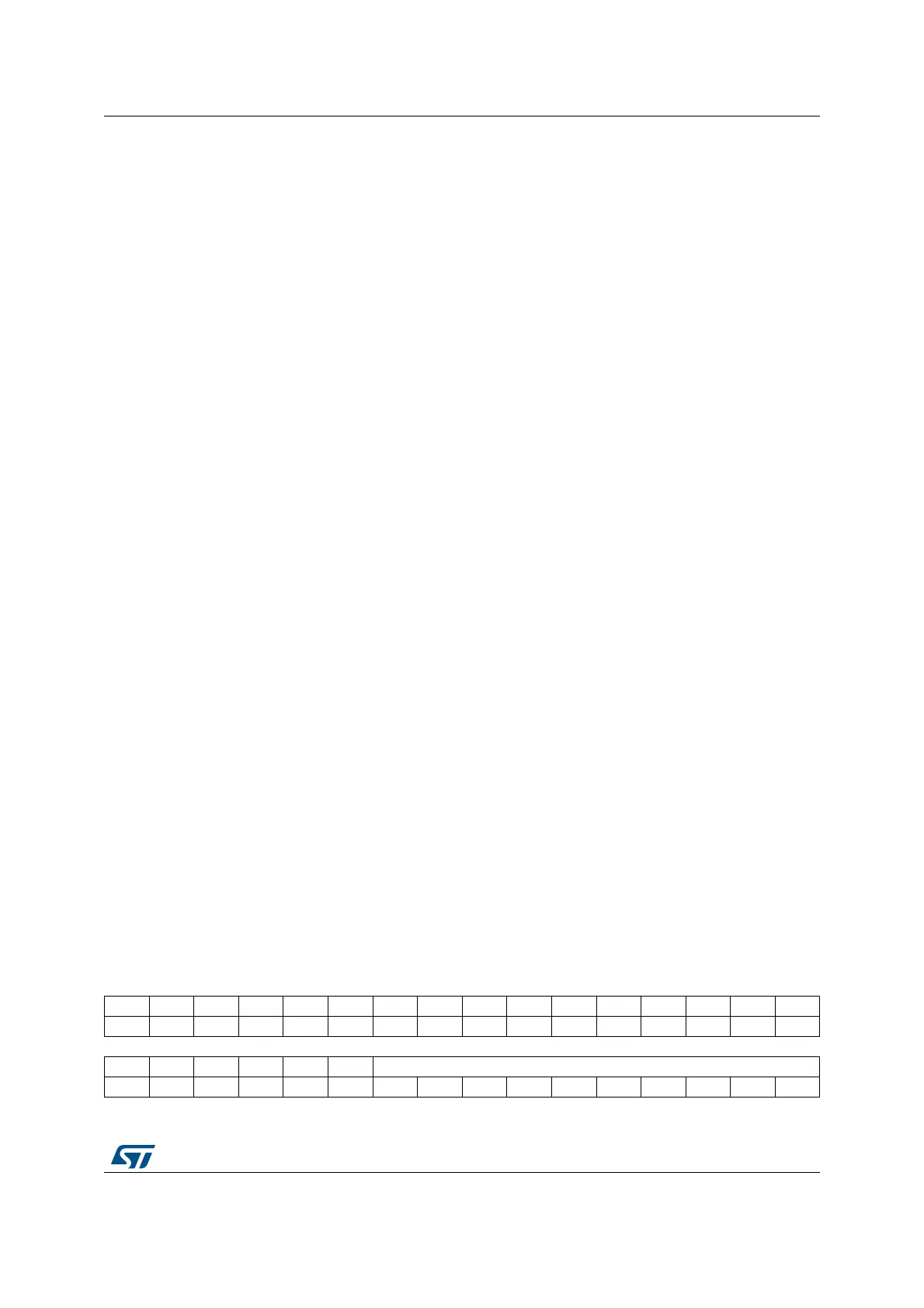
19.5.17 DAC Sample and Hold sample time register 1 (DAC_SHSR1)
Address offset: 0x40
Reset value: 0x0000 0000
Bits 18:16 MODE2[2:0]: DAC Channel 2 mode
These bits can be written only when the DAC is disabled and not in the calibration mode
(when bit EN2=0 and bit CEN2 =0 in the DAC_CR register). If EN2=1 or CEN2 =1 the write
operation is ignored.
They can be set and cleared by software to select the DAC Channel 2 mode:
– DAC Channel 2 in normal Mode
000: DAC Channel 2 is connected to external pin with Buffer enabled
001: DAC Channel 2 is connected to external pin and to on chip peripherals with buffer
enabled
010: DAC Channel 2 is connected to external pin with buffer disabled
011: DAC Channel 2 is connected to on chip peripherals with Buffer disabled
– DAC Channel 2 in sample & hold mode
100: DAC Channel 2 is connected to external pin with Buffer enabled
101: DAC Channel 2 is connected to external pin and to on chip peripherals with Buffer
enabled
110: DAC Channel 2 is connected to external pin and to on chip peripherals with Buffer
disabled
111: DAC Channel 2 is connected to on chip peripherals with Buffer disabled
Bits 15:3 Reserved, must be kept at reset value.
Bits 0:2 MODE1[2:0]: DAC Channel 1 mode
These bits can be written only when the DAC is disabled and not in the calibration mode
(when bit EN1=0 and bit CEN1 =0 in the DAC_CR register). If EN1=1 or CEN1 =1 the write
operation is ignored.
They can be set and cleared by software to select the DAC Channel 1 mode:
– DAC Channel 1 in normal Mode
000: DAC Channel 1 is connected to external pin with Buffer enabled
001: DAC Channel 1 is connected to external pin and to on chip peripherals with Buffer
enabled
010: DAC Channel 1 is connected to external pin with Buffer disabled
011: DAC Channel 1 is connected to on chip peripherals with Buffer disabled
– DAC Channel 1 in sample & hold mode
100: DAC Channel 1 is connected to external pin with Buffer enabled
101: DAC Channel 1 is connected to external pin and to on chip peripherals with Buffer
enabled
110: DAC Channel 1 is connected to external pin and to on chip peripherals with Buffer
disabled
111: DAC Channel 1 is connected to on chip peripherals with Buffer disabled
31 30 29 28 27 26 25 24 23 22 21 20 19 18 17 16
Res. Res. Res. Res. Res. Res. Res. Res. Res. Res. Res. Res. Res. Res. Res. Res.
1514131211109876543210
Res. Res. Res. Res. Res. Res. TSAMPLE1[9:0]
rw rw rw rw rw rw rw rw rw rw
 Loading...


