2
nd
Edition - Rev 0
SUPPLEMENT SG-1
CHAPTER 24 – DESCRITPION AND OPERATION
Page 5
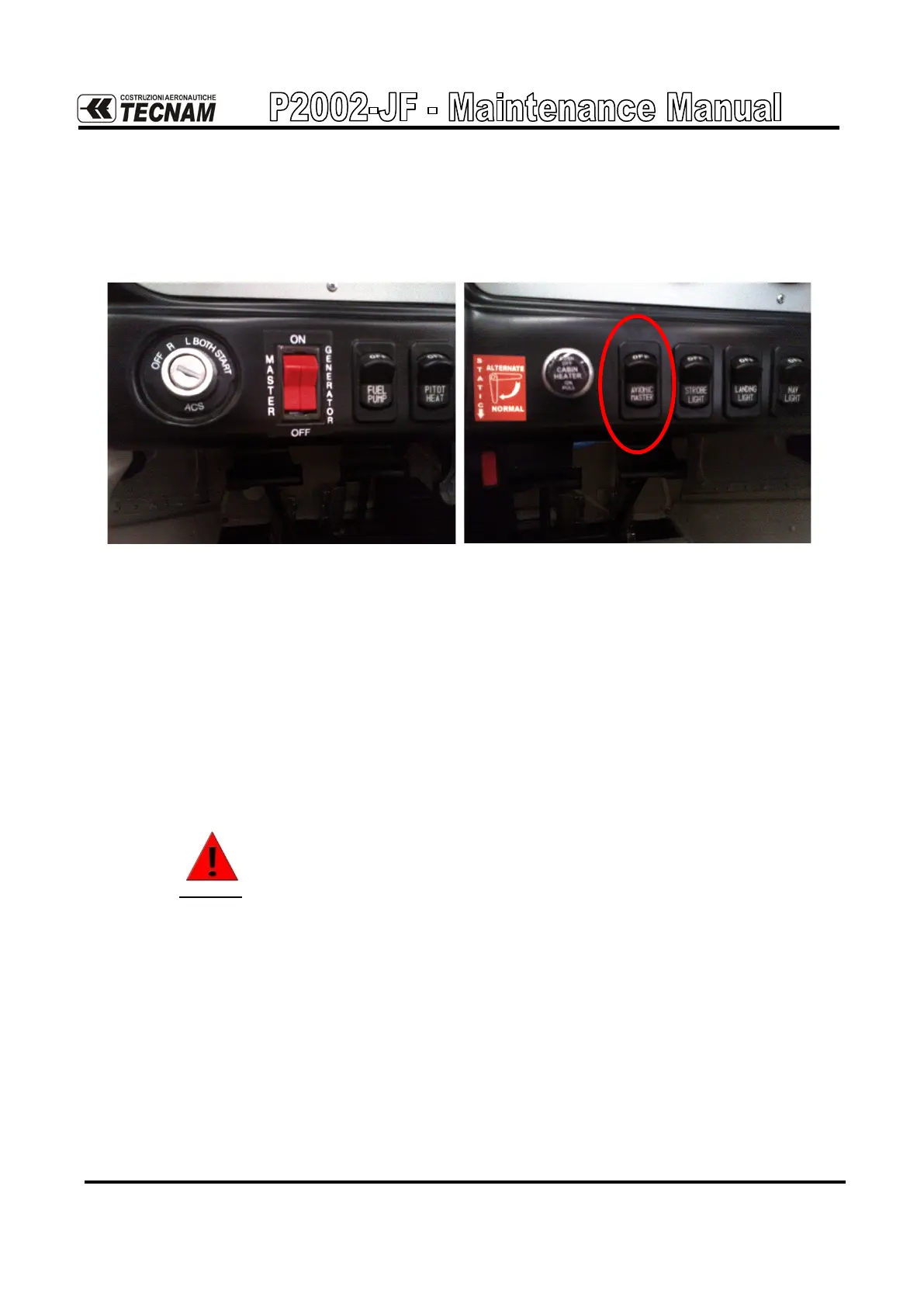
On the lower LH side of the instrument panel (see Figure below) the master
switches (Master and Generator) are located, beside the ignition key. On the
lower RH side of the instrument panel the Avionic Master switch is located.
Master switches and avionic master
The first two allow, respectively, to connect the battery through a relay to its
distribution bus and to provide the field signal to the alternator.
The second one allows, through a relay, the power supply of the loads connected
to the avionic bus.
The ignition switches (RH and LH) are activated through the ignition key which
also allows the engine starting.
WARNING
If ignition key is on L,R or ON position, a propeller movement
can cause the engine starting with consequent hazard for people
nearby.
Wiring diagrams are provided on Chapter 92 of this Supplement.