Page 2 2
nd
Edition – Rev 0
28-10
FUEL SYSTEM – DESCRIPTION AND OPERATION
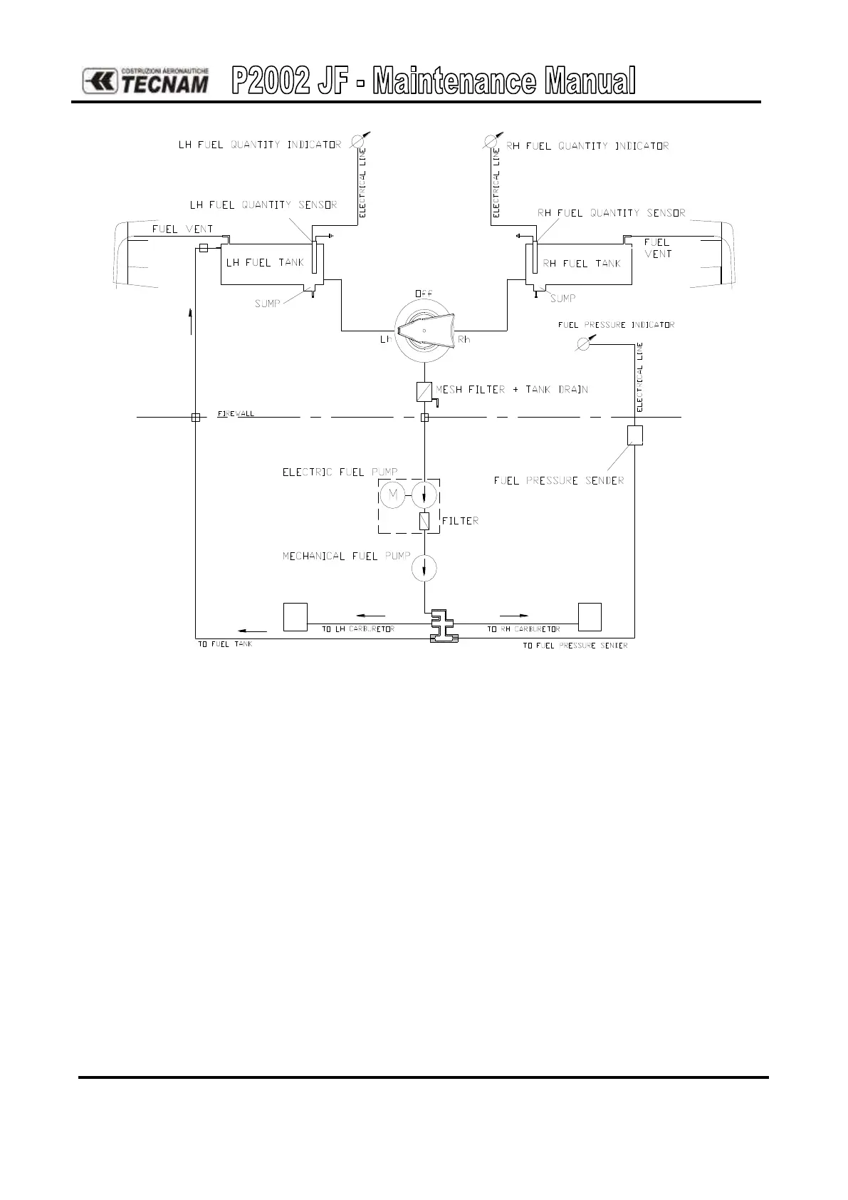
Figure 1 - Fuel system layout arrangement
The system is equipped with two aluminium fuel tanks (1) integrated within the wing box
and accessible for inspection through dedicated doors (2). Capacity of individual tank is 50lt
(13.5 Gal U.S.) . Each fuel tank is equipped with a drain valve located under the tank. Figure
2 illustrates the components of the fuel system.
In cabin, between the two pilots, is present a three positions fuel selector valve (5) (LEFT-
OFF-RIGHT). A strainer cup with a drainage valve (6) (Gascolator) is located below the
cabin’s floor near the firewall. Fuel level indicators for each tank are located on instrument
panel, each fuel tank is equipped with individual sensor-floats (3). Fuel feed is through an
engine-driven mechanical pump (8) and through an emergency electric pump (7). Electric
pump is equipped with a thin-mesh filter (7a) that can be accessed for inspection via the
closer cap (7b). An electric fuel pressure sender (12) is located on the engine’s side and fed
directly from the fuel manifold (11). The electric fuel pressure sender is connected to an
indicator on the instrument panel. The fuel manifold feeds the two carburettors, the fuel
pressure sender and the return line to the left tank. From the top of each tank there are pipes
that connect the fuel tank with the fuel vents (4) located on the wing tip trailing edge.