Page 2 2
nd
Edition – Rev 0
55-20
RUDDER – DESCRIPTION AND OPERATION
The rudder rotates via two hinges, (parts 6 and 7). At the top a ball bearing (6) let the
rudder to rotate. The bottom hinge pin rotates about a bushing (8) embedded within a
support flange attached to vertical stabilizer aft spar. A bellcrank (9) secured to the
rudder's lower hinge converts the rudder pedals cable commands.
The rudder is equipped with two end run stops made of Teflon (11).
Rudder mass balancing (10) is placed on the rudder upper rib’s horn. To inspect this
part it is necessary to remove the composite tip.
Control system layout is a steel cable driven and circuit terminates on rudder pedals and
then on the nose steering lever.
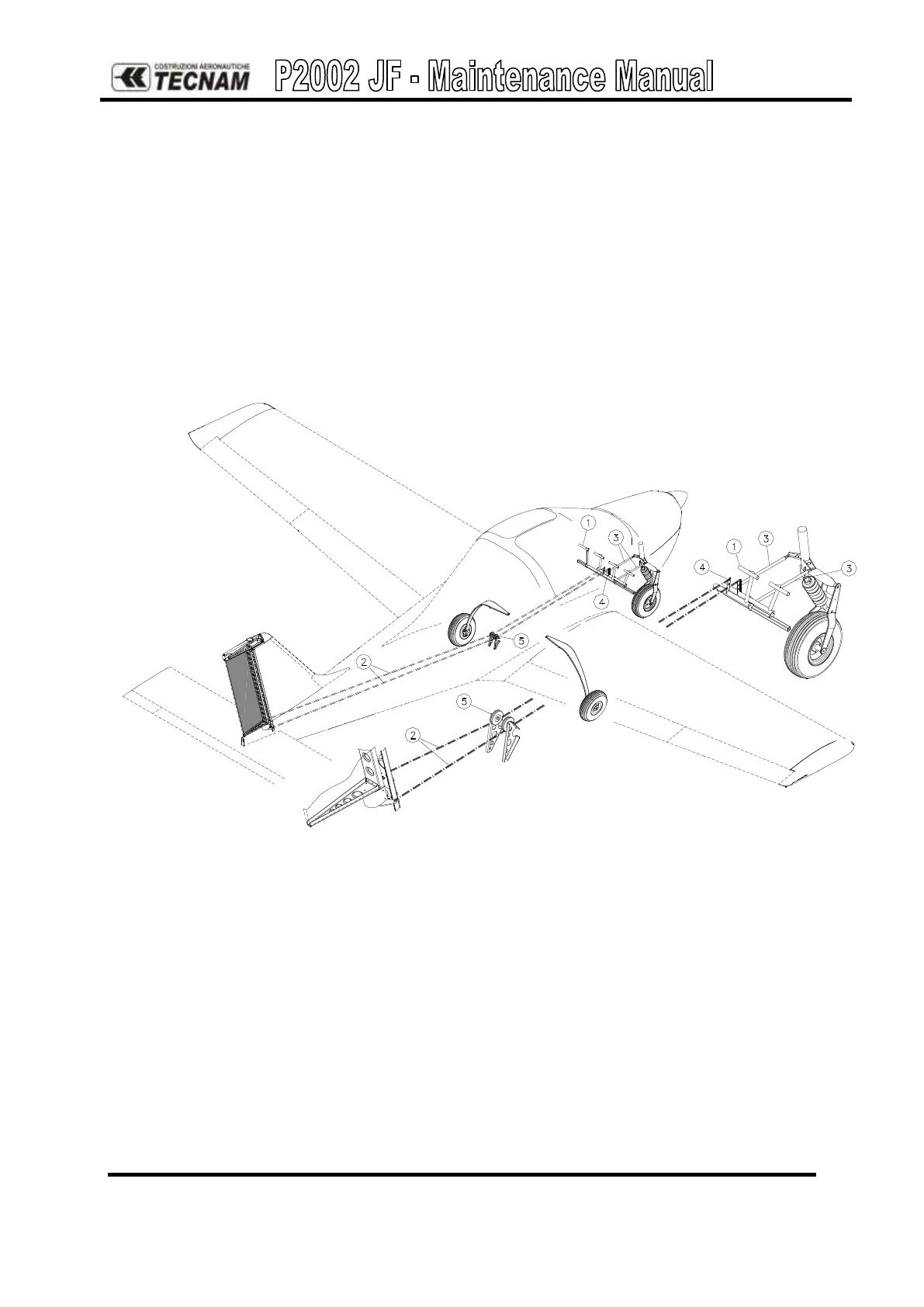
Figure 11. - Rudder and steering control
Rudder pedals (1) are attached to two pushrods (3) that transmit steering motion to the
nose gear leg through a lever. This lever hinges on the engine mount and springs
connected to the steering lever via two small plates allow for a more effective
realignment of the rudder. Length of pushrods can be modified via adjustable ball and
socket connections.